 |
|||
|
|
|||
|
Page Title:
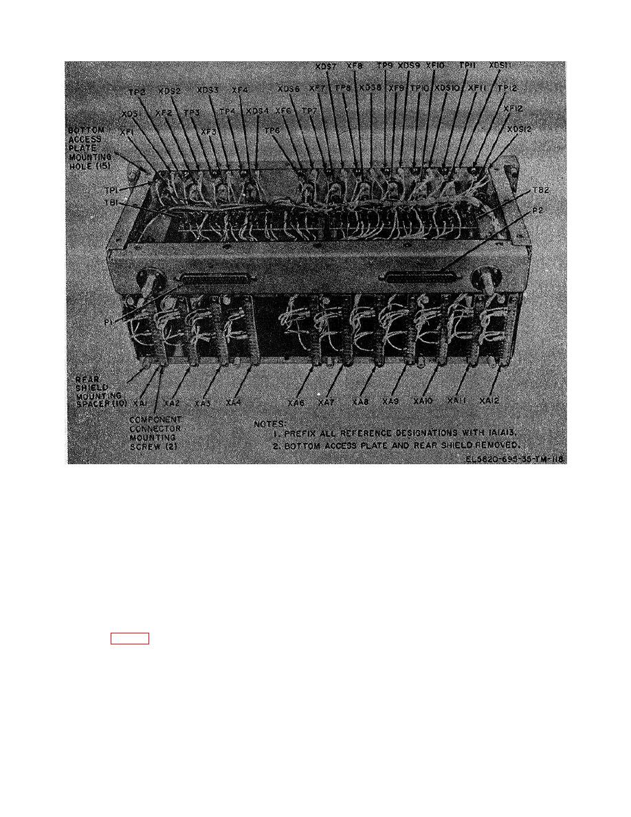
Figure 3-9. Power supply chassis assembly 1A1A13, parts location. |
|
||
| ||||||||||
|
|  TM 11-580-695-35
Figure 3-9. Power supply chassis assembly 1A1A13, parts location.
1A1A113 and pressing lamp end until mounted snugly
securing bottom access plate to power supply chassis
against power supply chassis assembly 1A1A13 frame.
assembly 1A1A13.
(2) Solder wires removed in step d(2) to
(2) Tag and unsolder wires connected to
lamp socket terminals.
lamp socket being removed.
(3) Mount and secure bottom access plate
(3) Force press fitted lamp socket through
to power supply chassis assembly 1A1A13 using the 15
its mounting hole in power supply chassis assembly
screws removed in step d(l).
1A1A13 by pressing terminal end toward mounting hole
and remove lamp socket from front of power supply
f. Removal and Replacement of Chassis
chassis assembly 1A1A13.
Mounted Connectors 1A1A13P1 or 1A1A13P2 (fig. 3-
9).
e. Replacement of Lamp Sockets 1A1A13XDS1
Through 1A1A1SXDS4 and 1A1A1SXDS6 Through
(1) Turn power supply chassis assembly
1A1A13 upside down and, remove the 15 screws
securing bottom access plate to power supply chassis
(1) Replace lamp socket by forcing terminal
assembly 1A1A13.
end of press fitted lamp socket through front of
mounting hole in power supply chassis assembly
3-40
|
|
Privacy Statement - Press Release - Copyright Information. - Contact Us |
