 |
|||
|
|
|||
|
Page Title:
Replacement of Parts on Meter Panel Assembly lA15A8 |
|
||
| ||||||||||
|
|  TM 11-5820-695-35
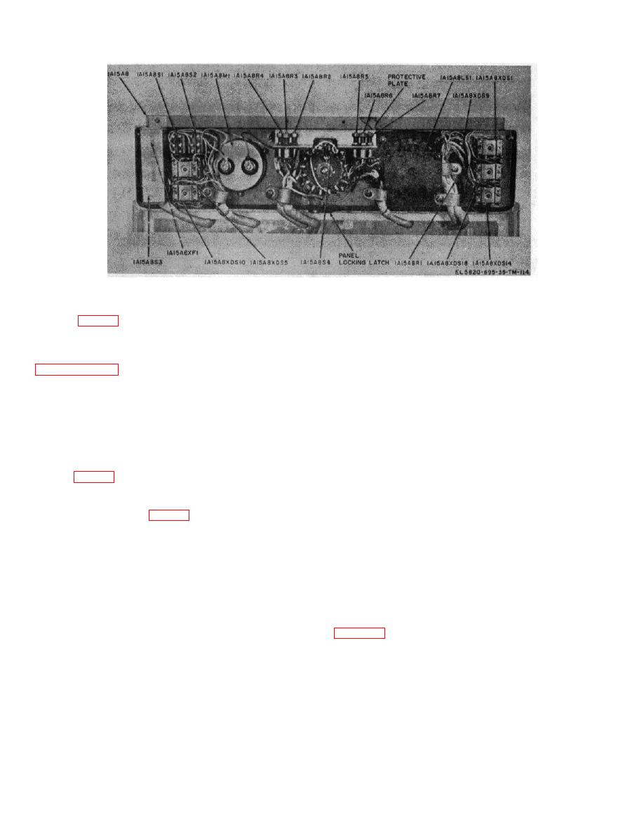
Figure 3-4. Meter panel assembly 1A15A8, rear view, parts location.
3-21. Replacement of Parts on Meter Panel Assembly
(2) Replacement.
lA15A8 (fig. 3-4)
(a) Position the new meter 1A15A8M1 in place
on meter panel assembly 1A15A8 and align the meter
Prior to removing and replacing parts on meter panel
mounting holes with those of the panel assembly.
assembly 1A5A8, perform the procedures listed in
(b) Secure the meter in place with the three
locknuts, screws, and washers removed in step (1) (g)
part is replaced, perform the procedures in paragraph 3-
above.
20b to restore equipment power.
(c) Position the meter panel assembly 1A15A8
upward and lock m position using the panel locking latch.
a. Replacement of Meter 1A15A8M1.
(d) Remove the two nuts, washers, and
shorting bar from the new meter terminals.
(1) Removal.
(e) Connect the wire lugs removed in step
(a) Loosen the two meter panel captive
(1)(d) above to their respective meter terminals and
screws (fig. 3-1).
fasten lugs to terminals with nuts and washers removed in
(1)(c) above.
(b) Swing the meter panel assembly
1A15A8 upward and lock it in an upright position by use of
(f) Place the shorting bar removed from the
the panel locking latch (fig. 3-4).
new meter on the terminal lugs of the old meter and
fasten in place with its terminal hardware.
(c) Remove the two nuts and washers
from the meter terminals.
(g) Release the meter panel assembly 1A15A8
and position it downward until it rests against electrical
(d) Tag and remove the wire lugs
equipment cabinet 1A15.
connected to the meter terminals.
(h) Secure the meter panel assembly 1A15A8
(e) Release the meter panel assembly
in place by finger tightening the two meter panel captive
1A15A8 and position it downward until it is perpendicular
screws.
to electrical equipment cabinet 1A15. Support or tie
meter panel assembly 1A15A8 in the perpendicular
position.
(f) Remove and save the three locknuts
and screws that secure meter 1A15A8M1 to meter panel
b.
Replacement of Indicator Light Assembly
assembly 1A15A8.
1A14A8XDS1, XDSS, XDS10, XDS14, or XDS18 (fig. 3-
4).
(g) Remove the meter from the meter
panel assembly.
3-35
|
|
Privacy Statement - Press Release - Copyright Information. - Contact Us |
