 |
|||
|
|
|||
|
Page Title:
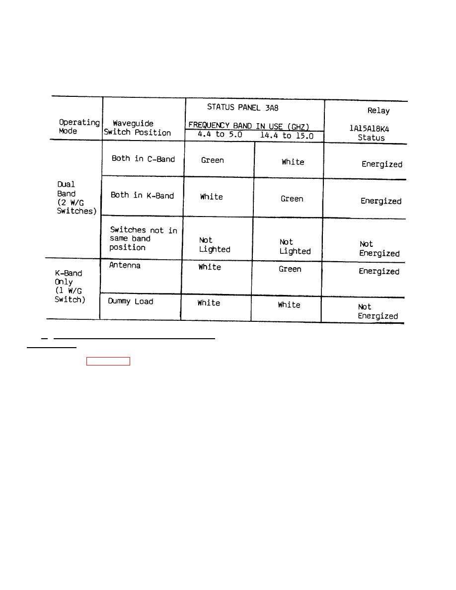
AN/GRC-144(V)4 Waveguide Switch Status Indications |
|
||
| ||||||||||
|
|  TM 11-5820-695-35
AN/GRC-144(V)4 Waveguide Switch Status Indications
waveguide switch terminal B to relay 1A15AlBK4 is
c. AN/GRC-144(V)4, K-Band Only (Optional
open circuit and relay K4 is not energized. In the
Configuration).
In this configuration, only one
antenna position, +28 Vdc is connected through the
waveguide switch is required; its positions are antenna
waveguide switch to 3A7J2-G and -R. The signal at
and dummy load. Figure 2-31 is a simplified schematic
3A7J2-G lights the K-band indicator (green) at STATUS
diagram of the connections. The waveguide switch is
PANEL 3A8. The signal at 3A7J2-R is applied to relay
shown in the dummy load position. In this position, +28
1A15A18K4 which is then energized. The chart above
Vdc is connected through the waveguide switch to
shows the STATUS PANEL indications and the
3A7J2-H to light the K-band (14.4 to 15.0) indicator
corresponding status-of relay 1A15A18K4 for both
(white) at STATUS PANEL 3A8. Connector 3A7J2-V
positions of the waveguide switch.
applies +28 Vdc constantly (not switched) to the C-band
(4.4 to 5.0) indicator (white) which is then always lighted
white in this configuration.
The connection from
Change 6 2-122
|
|
Privacy Statement - Press Release - Copyright Information. - Contact Us |
