 |
|||
|
|
|||
|
Page Title:
Digital Orderwire Demultiplexer lA1247 |
|
||
| ||||||||||
|
|  TM 11-5820-695-35
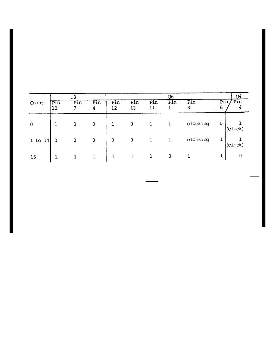
degree phase-shifted 16 kHz clock must be sampling
and U6-11 and U6-1 are logic 0. The logic 0 at U6-1
clamps U6-3 at logic 1 and counter U3 is disabled for up
DOW bits. Since DOW bits alternate between 1 and 0,
U6-8 will apply more logic O's at U3-5 than logic l's and
counting.
U3 will quickly count up to 15. While the count is
(7) The 32 Kb/s CVDOW signal is applied at
anywhere from 1 to 14, conditions are explained in
pin 2 of DVOW demultiplexer U7. The 16 KHz signal,
paragraph (4) above. The logic states of the counter
inverted U4-2, clocks the CVDOW signal through to U7-
signals and control gates are given in the chart below for
5. The 16 kHz clocking rate assures that only every
the three kinds of counter states.
other bit in DVDOW appears at U7-5. When the correct
(6) When the count reaches 15, U3-12 and
16 kHz clock phase has been selected, these will be
U3-7 are both logic 1. U6-12 and U6-13 are then logic 1
DVOW bits.
8, inverted in U4, is applied as logic 1 at U12-10. This
action is clocked by one cycle of the 52 kHz signal at
(8) The 16 kHz signal from U5-3 is divided by
U2, but the 32 kHz signal is applied at U12-11. Thus the
8 in ring counter U1O to provide the 2 kHz signal to
DOW transition signal (U4-8) always goes to logic 1
demultiplex the DOW signal. However, the 2 kHz signal
(U12-10) in coincidence with rising edges (logic 1) of the
must be phased to transitions in the DOW signal.
16 kHz and 32 kHz signal at U12-9 and U12-11. So
Inverter U4-8 provides the phase information and U12
U12-8 applies a reset pulse to U1O every time a DOW
provides the phase control of U10. Assuming the 16
transition is detected. This action synchronizes the 2
kHz signal has been set to the correct phase ((5)
kHz signal to DOW transitions.
above), U5-9 and U5-10 are sampling DOW bits. At
DOW transitions, U5-9 and U5-10 are both logic 1 or
both logic 0 ((1) (c) above). At that time, logic 0 at U5-
Change 6
2-24.11
|
|
Privacy Statement - Press Release - Copyright Information. - Contact Us |
