 |
|||
|
|
|||
|
|
|||
| ||||||||||
|
|  TM 11-5820-670-30
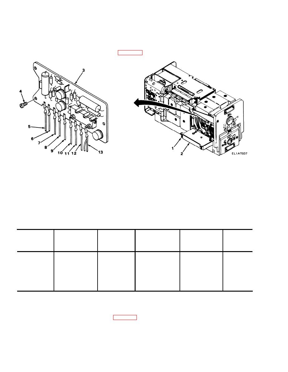
2-50. A2100 ASSEMBLY REPLACEMENT.
MATERIALS/PARTS: Regulator assembly, voltage, A2100 (P/N SMD41457)
PRELIMINARY PROCEDURE: Remove case (para 2-39).
REMOVAL
1. Using screwdriver, loosen two captive screws (1) and lower A4600 assembly (2).
2. Disconnect nine wire connectors from A2100 assembly (3).
3. Using screwdriver, remove three screws (4) and remove A2100 assembly (3).
INSTALLATION
1. Position A2100 assembly (3) on chassis and install three screws (4).
2. Using screwdriver, tighten three screws (4).
3. Connect nine wire connectors as shown in table below.
POSITION ON
POSITION ON
ASSEMBLY
WIRE COLOR
INDEX NO.
ASSEMBLY
WIRE COLOR
INDEX NO.
1
GRN
5
6
ORG
10
2
WHT/BLU
6
7
WHIT/VIO
11
3
WHT/GRN
7
8
WHT/GRY
12
4
WHT/RED
8
BLK & BLK
9
13
5
YEL
9
(2 wires)
4. Raise A6400 assembly (2) into position.
5. Using screwdriver, tighten two captive screws (1).
FOLLOW-ON MAINTENANCE: Install case (para 2-39).
2-164
|
|
Privacy Statement - Press Release - Copyright Information. - Contact Us |
