 |
|||
|
|
|||
|
|
|||
| ||||||||||
|
|  TM 11-5820-670-30
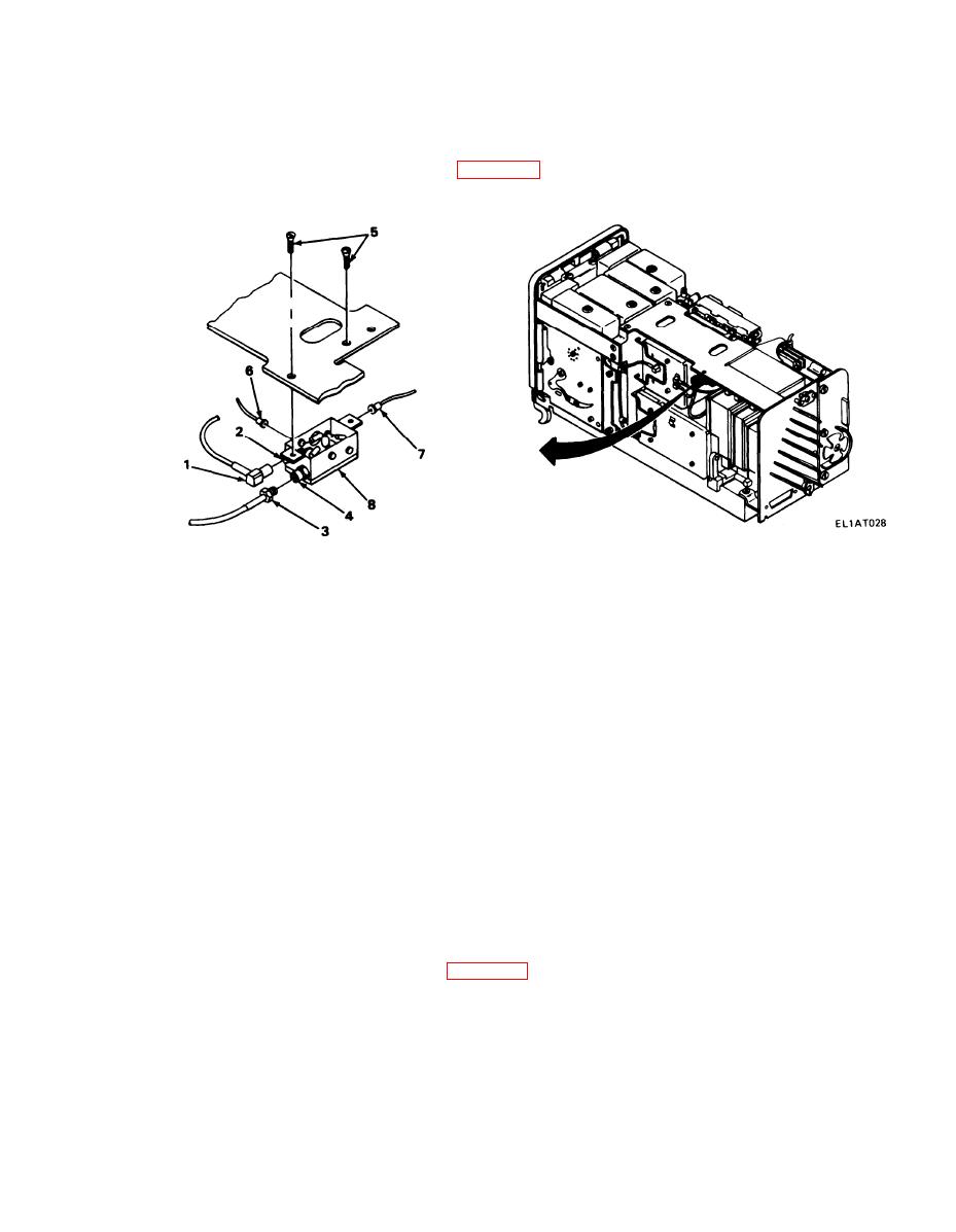
2-46. A6600 ASSEMBLY REPLACEMENT.
MATERIALS/PARTS: Amplifier assembly, isolation, A6000 (P/N SMD619913)
PRELIMINARY PROCEDURE: Remove case (para 2-39).
REMOVAL
1. Disconnect yellow wire (P6601) (1) from J6601 (2).
2. Using two wrenches, disconnect yellow wire (P6003) (3) from screw connector (4).
3. Using screwdriver, remove two screws (5).
4. Disconnect black wire connector (6) from color-coded plug.
5. Disconnect orange wire connector (7) from color-coded plug.
6. Remove A6600 assembly (8).
INSTALLATION
1. Connect orange wire connector (7) to color-coded plug.
2. Connect black wire connector (6) to color-coded plug.
3. Position A6600 assembly (8) under bracket and install two screws (5).
4. Using screwdriver, tighten two screws (5).
5. Connect yellow wire (P6003) (3) to screw connector (4).
6. Using two wrenches, tighten yellow wire (P6003) (3) and connector (4).
7. Connect yellow wire (P6601) (1) to J6601 (2).
FOLLOW-ON MAINTENANCE: Install case (para 2-39).
2-177
|
|
Privacy Statement - Press Release - Copyright Information. - Contact Us |
