 |
|||
|
|
|||
|
|
|||
| ||||||||||
|
|  TM 11-5820-670-30
2-44. A5500 MODULES AND ASSEMBLY REPLACEMENT. (CONT)
INSTALLATION
1. Position assembly (9) in hinge (8).
2. Install hinge pin (7) in hinge (8) from bottom.
3. Install C-clip (6) in hinge pin (7).
NOTE
If modules were not removed from assembly, proceed to step 12 for installation of
assembly.
Relays K5501 through K5505 are held into sockets by a holddown clamp. Steps 4, 5, and 6 are typical
for all relays.
Relay K5502 is P/N SMC413823 while all other relays are P/N SMC413824.
4. Aline pins on relay (4) with holes in socket (5) and push into place.
5. Position holddown clamp (3) over relays and install screw (1) and Iockwasher (2).
6. Using screwdriver, tighten screw (1).
EL1AT020
NOTE
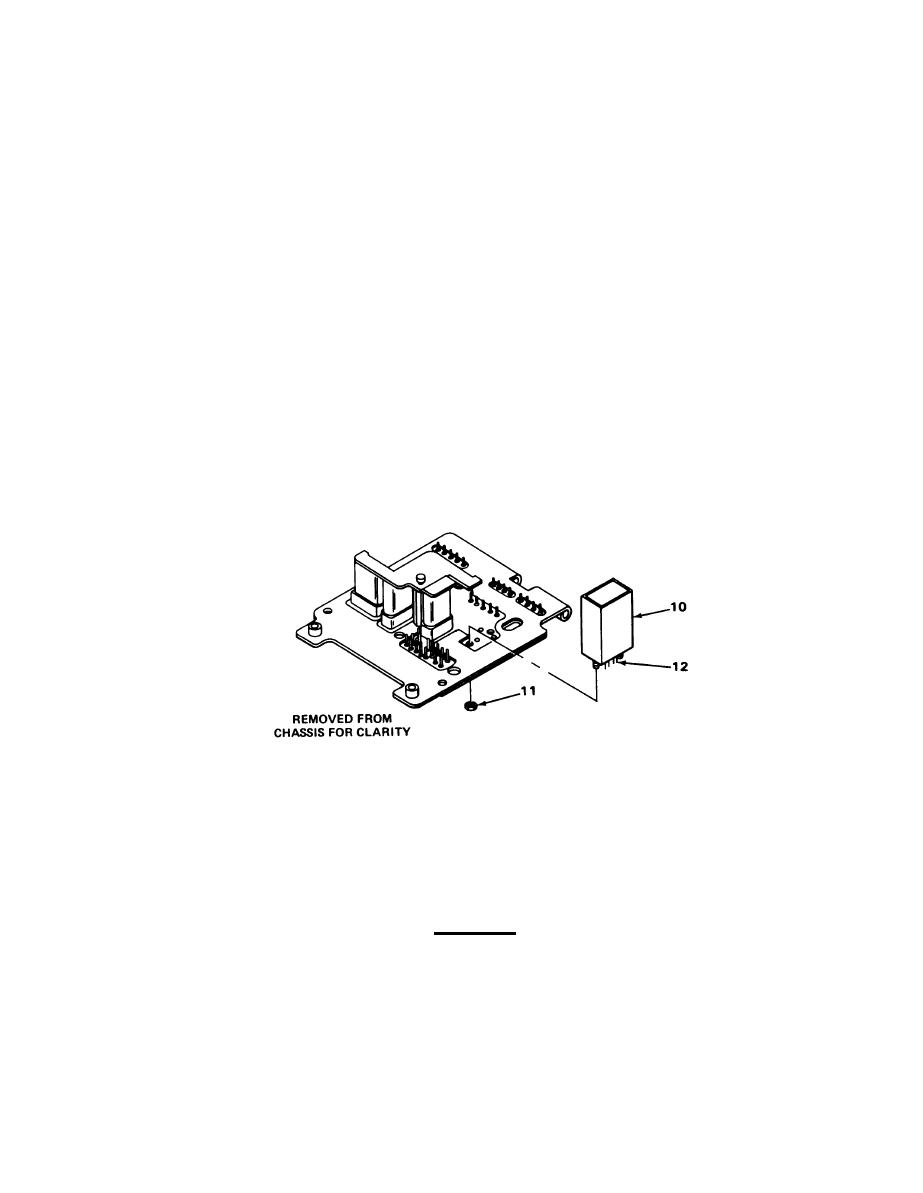
Filter module is secured with locknuts and is soldered to printed circuit board.
7. Position module (10) on board and install locknuts (11).
8. Using wrench, tighten locknuts (11).
CAUTION
Care must be taken when performing next step to prevent damaging printed circuit
board.
2-169
|
|
Privacy Statement - Press Release - Copyright Information. - Contact Us |
