 |
|||
|
|
|||
|
|
|||
| ||||||||||
|
|  TM 11-5820-670-30
2-35. RECEIVER SENSITIVITY ADJUSTMENTS. (CONT)
EL1AT244
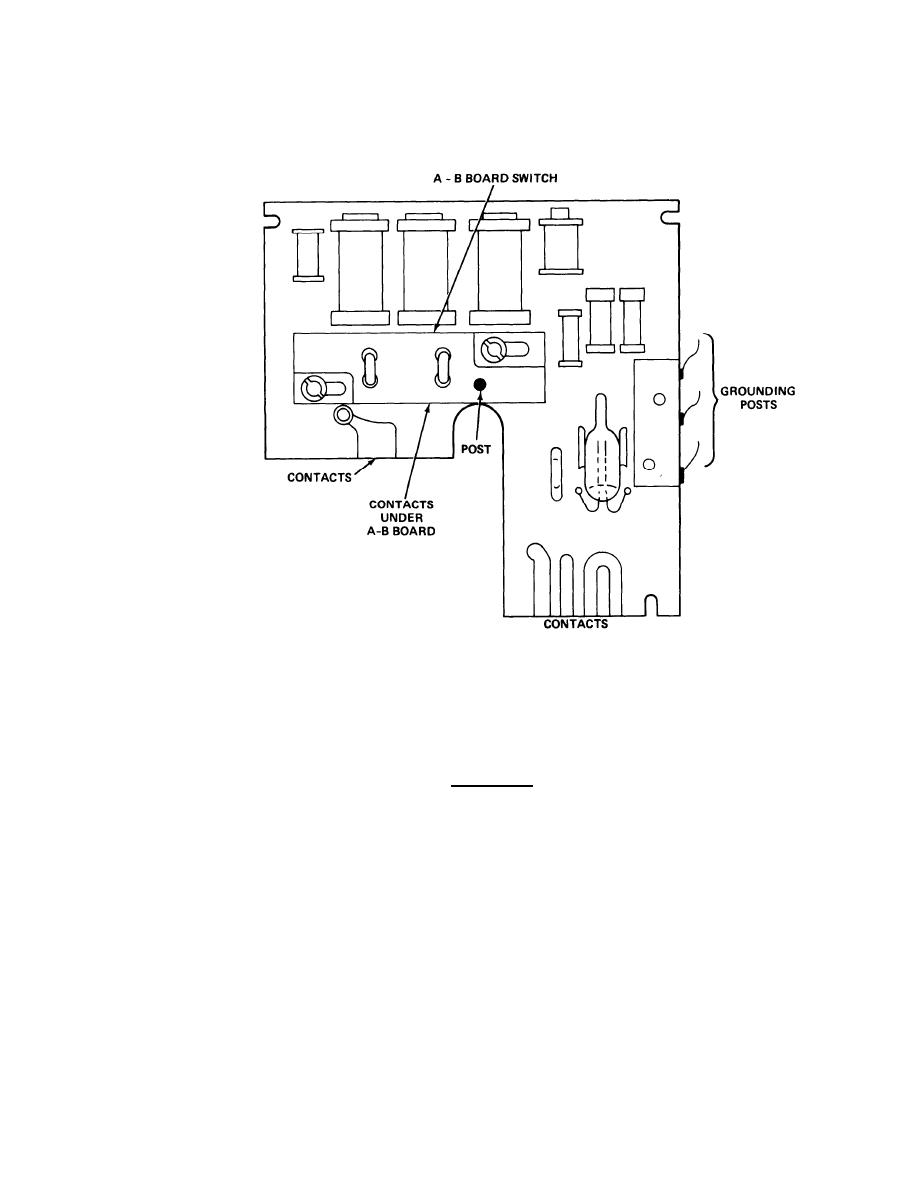
6. Using board extractor, remove A1100 module from its mount. Inspect A-B board switch for a
broken post. If post is broken, replace module. Clean contacts by rubbing with a pencil
eraser. Ensure grounding posts are in direct contact with A1000 can.
CAUTION
If post on A-B board switch does not fit in fork, the post will be broken the first time band
switch actuator changes position, and receiver will not work.
7. Position band switch so post will fit into fork on band switch actuator, then reinstall
module.
8. Repeat steps 6 and 7 for A1200 module, then A1300 module, taking care to insert post into
fork in band switch actuator when reinstalling each module.
2-143
|
|
Privacy Statement - Press Release - Copyright Information. - Contact Us |
