 |
|||
|
|
|||
|
Page Title:
RECEIVER SENSITIVITY ADJUSTMENTS. |
|
||
| ||||||||||
|
|  TM 11-5820-670-30
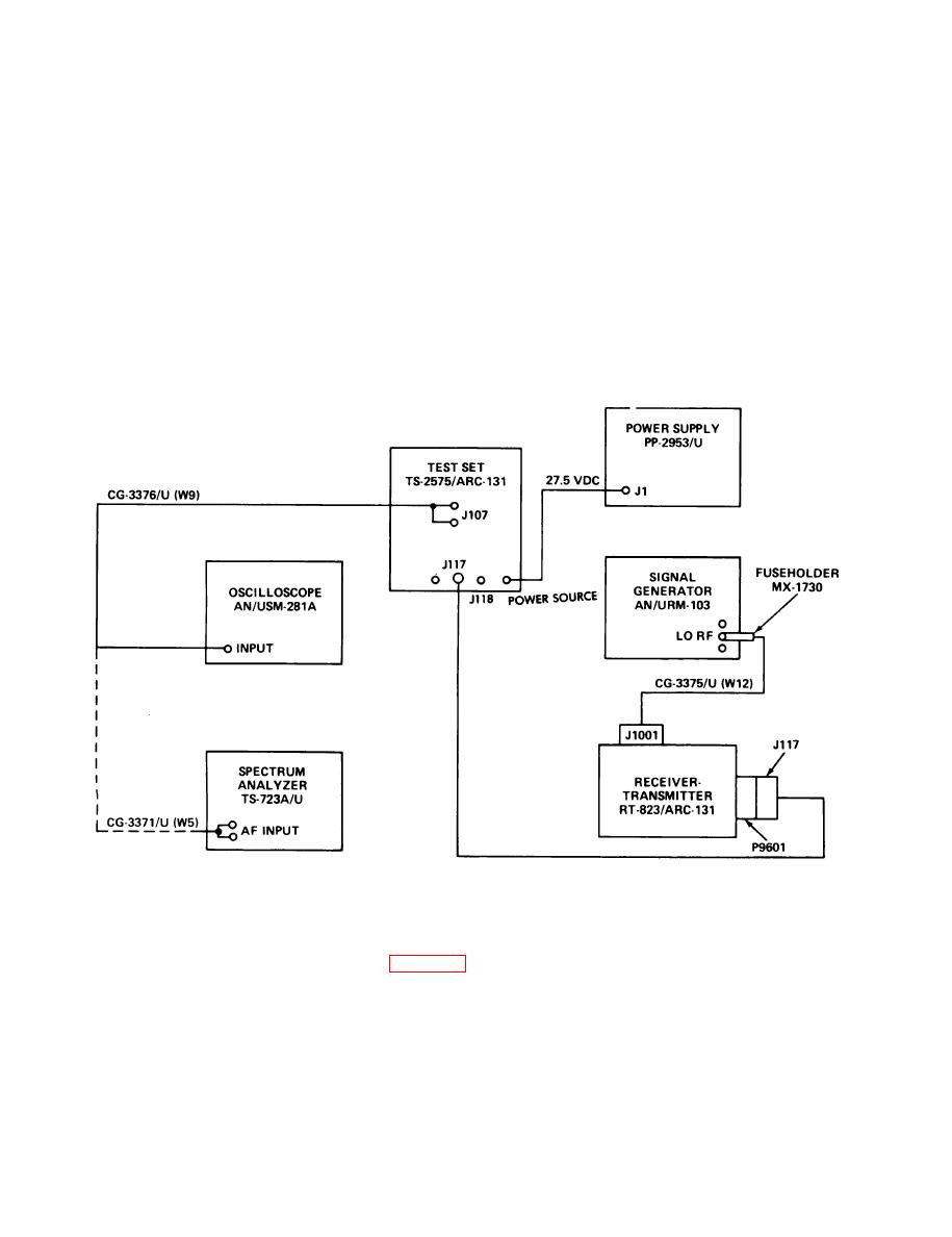
RECEIVER SENSITIVITY ADJUSTMENTS.
TEST EQUIPMENT AND MATERIALS
Maintenance Kit MK-1035/ARC-131
Signal Generator AN/URM-103
Oscilloscope AN/USM-281A
Power Supply PP-2953/U
Fuseholder MX-1730/U
Spectrum Analyzer TS-723A/U.
All cables are part of MK-103/ARC
TEST SETUP
Connect equipment as shown in test setup diagram. Turn on all equipment and allow at least 5 minutes
for warmup.
EL1AT243
ADJUSTMENT PROCEDURE
1. Set control unit C-7088/ARC-131 mode switch on test set to OFF.
2. Remove cover from A1000 VHF TUNER (para 2-68).
3. Set control unit SQUELCH switch to DIS, mode switch to T/R, and frequency selectors to
30.00 MHz.
4. Set signal generator AN/URM-103 to 30.00 MHz with 8 kHz deviation and 1000 Hz modulation.
5. Lower rf attenuator of signal generator until signal drops off. If sine wave on oscilloscope
and audio voltage on distortion analyzer drop off with considerable static before 0.5 microvolt,
perform steps 6, 7, and 8.
2-142
|
|
Privacy Statement - Press Release - Copyright Information. - Contact Us |
