 |
|||
|
|
|||
|
|
|||
| ||||||||||
|
|  TM 11-5820-670-30
2-10. RECEIVER TONE SQUELCH SENSITIVITY TEST. (CONT)
12. Reduce AN/URM-103 output level until audio output indication disappears, and observe
AN/URM-103 output level (squelch dropout).
STANDARD. 0.4 microvolt
13. If AN/URM-103 output level does not indicate 0.4 microvolt, see troubleshooting chart 2-12.
14. Repeat steps 1 through 14, adjusting the TS-2575/ARC-131 for each of the following
frequencies: 41.00 MHz, 52.00 MHz, 53.00 MHz, 65.00 MHz, and 75.00 MHz.
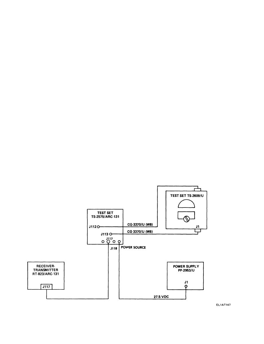
2-11. TRANSMITTER POWER OUTPUT TEST.
PURPOSE
This test checks the rt's ability to transmit a modulated rf carrier with sufficient power. Radio is keyed,
and power output is measured with a wattmeter.
TEST EQUIPMENT AND MATERIALS
Maintenance Kit MK-1035/ARC-131
Radio Frequency Power Test Set TS-2609/U
Power Supply PP-2953/U
All cables are part of MK-1035/ARC
TEST SETUP
Connect equipment as shown in test setup diagram. Turn on ail equipment and allow at least 5 minutes
for warmup.
2-22
|
|
Privacy Statement - Press Release - Copyright Information. - Contact Us |
