 |
|||
|
|
|||
|
|
|||
| ||||||||||
|
|  TM 11-5820-554-12
ELODOO38
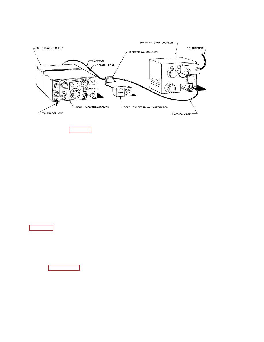
Figure 12-2. CU-2004/U and Collins KWM-2/2A, hookup diagram.
marked SHUNT. Connect the ground strap from the
terminal marked SERIES to the ground terminal.
Set the ANT OUTPUT C control to 24-00. Set the
SERIES COIL to zero.
Keep the antenna lead-in inside the building as short
as possible. If the coupler is used inside an aircraft,
REFLECTED position (or use an swr meter).
the lead-in inside the aircraft should be as short as
g. Set the Collins KWM-2/2A EMISSION
12 inches. This lead length influences the selection
switch to LOCK.
of a mounting position for the coupler. With a
h. With the COAX INPUT C control maintain
heavy conductor such as shield braid, attach the
the Collins KWM-2/2A plate current at maximum,
GROUND terminal of the coupler to a good ground.
but no higher than 210 ma.
Ground radials buried below the surface of the
i. With the SERIES COIL control, find the
ground may be necessary. If the installation is in an
plate current dip, and watch the reflected power
aircraft, attach the ground wire to the skin of the
indication at the same time.
aircraft.
j. When properly tuned, the COAX INPUT C
control will maintain loading and should be set for
12-4. Tuning Procedure
plate current between 200 and 230 ma. The
a. Connect the Collins KWM-2/2A, 302C 3
directional wattmeter and antenna coupler as shown
and should be used to dip the plate current and the
in figure 12-2. Leave the coaxial lead disconnected
reflected power indications to minimum.
from the coupler at this time.
k. If the COAX INPUT C control reaches
b. Connect a dummy load to the coaxial lead
maximum (dial reads 10), add in one of the 500-f
from the directional coupler. Use any 50-ohm load
capacitors, using one of the COAX INPUT C
capable of dissipating the power output expected
from the transmitter.
l. If a unity swr still cannot be obtained,
c. Tune and load the Collins KWM-2/2A
connect the antenna to the terminal marked SERIES,
according to paragraph 3-12.
and repeat h, i, and k above at the same time
d. Remove the dummy load from the circuit,
adjusting the ANTENNA OUTPUT C along with
and connect the coaxial lead to the antenna coupler
the controls in h and i above. (Maximum C is
in place of the dummy load.
obtained when the dial reads O.)
SPARE jacks. Set the COAX INPUT C dial to
zero. Connect the wire antenna to the terminal
12-2
|
|
Privacy Statement - Press Release - Copyright Information. - Contact Us |
