 |
|||
|
|
|||
|
Page Title:
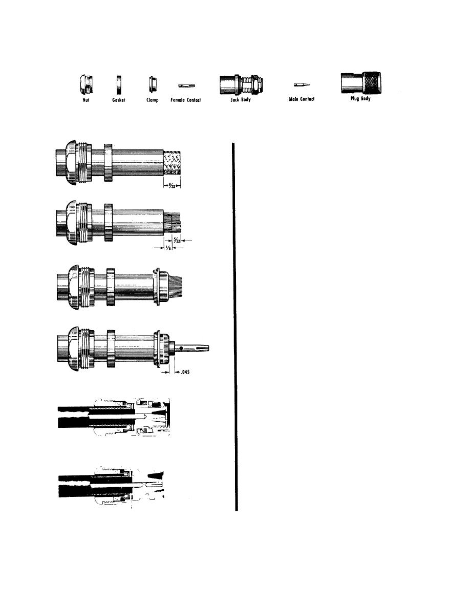
Figure 11-1. Connector assembly instructions. |
|
||
| ||||||||||
|
|  TM 11-5820-554-12
Place nut and gasket over cable and cut off jacket
9/32" from end.
Comb out braid and fold out. Cut off cable dielectric
flush 1/8" from end of jacket.
Pull braid wires forward and taper toward center
conductor. Place clamp over braid and push back against
cable jacket.
Fold back braid wires as shown, trim to proper length and
form over clamp as shown. Solder contact to center
conductor.
Insert cable and parts into connector body. Make sure
sharp edge of clamp seats properly in gasket. Tighten
nut.
EL000054
Figure 11-1. Connector assembly instructions.
11-3
|
|
Privacy Statement - Press Release - Copyright Information. - Contact Us |
