 |
|||
|
|
|||
|
Page Title:
Operation Outside Amateur Bands |
|
||
| ||||||||||
|
|  (6) When receiving, leave the A.F. GAIN
TM 11 - 5820-554-12
control (5) set for a comfortable monitoring level,
(6) Set the OFF-ON-NB-CAL switch (1) to ON.
and adjust the receive level with the R.F. GAIN
The Collins KWM-2/2A is now ready for transmit
control (10). When the Collins KWM-2/2A is
operation in ssb service.
Speaking into the
receiving, the received signal is indicated in S-units.
microphone transfers from receive function to
The S-meter will read correctly with the R.F. GAIN
transmit function through the vox circuit action. If
control (10) at less than maximum setting, provided
the receiver is tuned to a different frequency, the
the received signal level is high enough to actuate the
transmitter is also tuned to this new receiver
S-meter. For example, if the R.F. GAIN control
frequency.
(10) is set for no-signal reading of S8 and reads S9
(7) After changing frequency, set the
with signal, the received signal is S9.
EMISSION switch (2) to LOCK and make the
d. Mobile Operation. The vox and antivox
following checks:
circuits will operate in mobile operation, but push-
(a) Set the meter switch (8) to grid.
to-talk operation is recommended, since high level
background noises will produce undesirable vox
slightly to check to see that the pa grid drive is
switchover. Set the VOX GAIN and ANTIVOX
peaked. If not, repeat a(10) above.
GAIN controls fully counterclockwise before
(c) Set the meter switch (8) to PLATE, and
installation. If vox operation is desired, leave
check the dip in plate current with the P.A.
clearance in installation so the top cover can be
TUNING control (7).
opened. For mobile operation, load the power
(d) Set the EMISSION switch (2) back to the
amplifier to 210 ma plate current. (In some
desired operating position.
installations, power amplifier plate current readings
c. Cw Operation.
less than 210 ma will be obtained due to cable
NOTE
length, cable size, and battery condition.)
The cw output signal is 1,750 Hz higher
3-13. Operation Outside Amateur Bands
than the dial reading. To set the cw output
signal frequency, subtract 1,760 Hz from
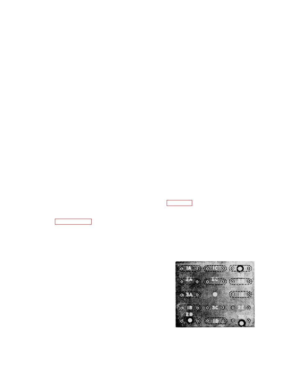
a. Selection of Crystals. The crystals supplied in
the desired output signal frequency. Set
Crystal Unit Set, Quartz CK-31/FRC-93 cover the
the crystal and vfo dial for the resultant
frequency ranges of 3.4 to 5.0 MHz and 6.5 to 30
output in cw operation.
MHz. Figure 3-6 shows crystal socket locations.
(1) Set the OFF-ON-NB-CAL (1) switch to ON.
Select these crystals as follows:
(2) Set up receiver and transmitter operation
(1) If the lower edge of the desired 200-kHz
according to paragraph 3-11 and a above, with
band is 11.8 MHz or less, the required frequency is
EMISSION switch (2) set to CW.
equal to the lower edge of the desired band plus
(3) Press the key and adjust the A.F. GAIN
3.155 MHz. For example, if the desired band is 4.0
control (5) for comfortable monitoring level.
to 4.2 MHz, 4.0 MHz plus 3.155 MHz equals 7.155
(4) Hold the key down and increase the VOX
MHz.
GAIN control setting until the vox relay operates.
(2) If the lower edge of the desired 200-kHz
To change the release time constant, adjust the VOX
band is 12.00 MHz or higher, the required
TIME
CONSTANT
potentiometer
(R43).
Clockwise rotation of this control increases the
release time. This control is located on a bracket
under the top cover, behind the meter.
(5) Set the meter switch (8) to ALC. While
sending a series of dots, adjust the MIC GAIN
control (4) for S3 meter reading of ALC.
NOTE
Component heating during operation may
cause the ALC reading to decrease.
Maintain the ALC reading at S3 by
Figure 3-6. Crystal socket locations
adjusting the MIC GAIN control (4) as
required.
3-11
|
|
Privacy Statement - Press Release - Copyright Information. - Contact Us |
