 |
|||
|
|
|||
|
Page Title:
Initial Settings and Adjustments. |
|
||
| ||||||||||
|
|  TM 11-5820-509-35
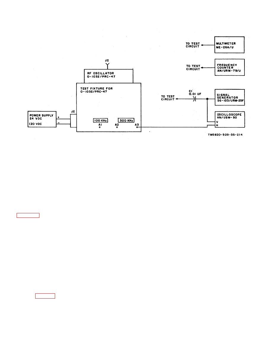
Figure 6-15. RF Oscillator O-1032/PRC-47 (A8A6), Performance Tests, Initial Test Equipment Connections.
(4) Place the +20V ON-OFF switch on the
c. Initial Settings and Adjustments.
test fixture to ON; then set the signal generator output
(1) Connect the multimeter dc probe to test
frequency to 3.000 MHz.
point J2 on the module and record the reading obtained.
(5) Using the rf probe of the multimeter,
This value must be 17.5 1.0 volts dc.
adjust the signal generator output level {at the base of
(2) Press the PUSH TO READ pushbutton on
locked oscillator Q4) to the value measured in step c (3)
the front of the test fixture and read the current drawn by
above.
the module. The +20V CURRENT meter must read
35.0 5.0 milliamperes.
NOTE
(3) Connect the multimeter rf probe and the
Be sure to maintain this output level
frequency counter to the junction of Q4, R23, and R24
for the remainder of this test.
(6) A stable 6:1 Lissajous pattern must be
temperature compensated oscillator. This voltage shall
obtained on the oscilloscope. If not, perform the locked
not be less than 0.3 volt rms and the output frequency
oscillator and 500-kHz amplifier adjustments in step e
shall be approximately 3.0 MHz.
before continuing.
NOTE
(7) Vary the signal generator frequency from
Do not adjust or calibrate the
2.90 to 3.10 MHz while observing-the oscilloscope
temperature compensated oscillator
display. The 6:1 Lissajous pattern must remain clear
at this time.
Final calibration
and stable throughout the signal generator output
procedures are detailed in step g.
frequency excursion.
d. Locked Oscillator, Divider, and Output Amplifier
(8) Connect the rf probe of the multimeter to
Performance.
test jack J3 on the module and record the 500 kHz
output voltage. Repeat the measurement at test jack J4
(1) On the test fixture, place the +20 ON-OFF
on the module. The multimeter shall read 1.5 0.2
switch to OFF.
volts rms. If not, perform the locked oscillator and 500
(2) Carefully disconnect the inner conductor
kHz amplifier adjustments in step e before continuing.
of the miniature coaxial cable from the junction of Q4-
(9) Connect the vertical input of the
R23-R24 (fig. 3-53).
oscilloscope to the 100 KHZ A1 connector on the front
(3) Connect the frequency counter to the
panel of the test fixture. (Do not disturb the signal
output of the signal generator; then connect the open
generator and frequency counter con nections in the
end of capacitor C1 to the terminal in the module from
module.)
which the coaxial cable was disconnected.
6-28
|
|
Privacy Statement - Press Release - Copyright Information. - Contact Us |
