 |
|||
|
|
|||
|
Page Title:
Initial Settings and Adjustments. |
|
||
| ||||||||||
|
|  TM 11-5820-509-35
Personal injury or death can result.
+19V. Then place the BLOWER ON-OFF switch to ON
Be careful.
and set 115VAC ON-OFF switch to ON. Observe that
the text fixture blower is running, and 115 VAC lamp is
NOTE
lit.
Perform the initial adjustments and
WARNING
each of the following tests in the
Voltages to 1500 volts are present in
order listed to avoid erroneous test
the PP-3518/PRC-47 power supply
results or maladjustment of the
module.
control settings.
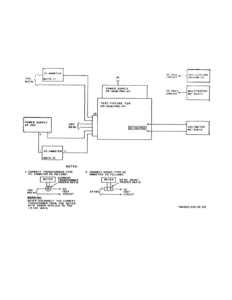
Figure 6-14. Power Supply PP-3518/PRC-47 (A8A5 ), Performance Tests, Initial Test Equipment Connections.
(3) Place the HV ON-OFF switch to OFF,
c. Initial Settings and Adjustments.
return the VOLTAGE SEL switch on the test fixture to
(1) Rotate the VOLTAGE SEL switch to all
+19V position, and apply primary power to the Harrison
positions and note that an indication is obtained on the
6434B power supply. Then place the test set +23V ON-
DC VOLTAGE meter only at the +19V, +23V, and
OFF switch to ON
+26.5V positions. (Ignor the ac voltmeter at this timed)
(4) Connect the multimeter to the output
(2) Place the HV ON-OFF switch to ON and
terminals of the Harrison 6434B power supply and adjust
note that an indication is obtained on the DC VOLTAGE
the terminal voltage to 23.0 0.25
meter in all positions of the VOLTAGE SEL switch
except FIL The ac voltmeter indicates approximately 6.3
volts when VOLTAGE SEL is in the FIL position.
6-25
|
|
Privacy Statement - Press Release - Copyright Information. - Contact Us |
