 |
|||
|
|
|||
|
Page Title:
Initial Settings and Adjustments. |
|
||
| ||||||||||
|
|  TM 11-5820-509-35
(5) Adjust the output of the -7 volts power
(7) Set the IMPEDANCE switch on the output
meter to 300 OHMS, and adjust the meter multiplier for
supply using the SIDETONE GATE TEST jack (J3) and
the SIDETONE GATE ADJUST control on the test
5000 milliwatts full scale.
fixture. The reading at J3 must be set to -7.0 0.2 volts
NOTE
dc. Then place the power control switch on the -7 volts
Perform the initial adjustments and
power supply to off.
each of the following tests in the
(6) Permit the test equipment and the module
order listed to avoid erroneous test
to stabilize for at least 5 minutes before beginning the
results or maladjustment of the
following procedures.
module gain settings.
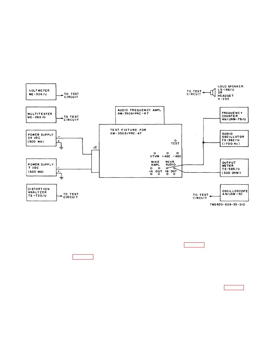
Figure 6-11. Audio Frequency Amplifier AM-3506/PRC- 47 (A8A 7 ) Performance Tests, Initial Test Equipment
Connections
c. Initial Settings and Adjustments.
(5) Reduce the output level of the audio
oscillator to 0. Reset it to 0.010 0.002 volt rms at
(1) Set the audio oscillator output frequency
MIKE AMPL IN jacks (J5 and J11) and adjust
to 1700 Hz and adjust the output level to 0.1 volt rms at
potentiometer R40 (fig. 3-94) until the VOX ON lamp
RCVR AUDIO IN jacks (38 and J14).
(DS2) on the test fixture lights
(2) Observe the output meter and adjust
(6) Move the oscilloscope input to RCVR
receiver gain control R54 (fig. 3-94) until the meter
AUDIO OUT jacks (J7 and J13). Energize the- 7 volts
reads 1.0 watt output (18.0 volts rms) at RCVR AUDIO
dc power supply and reset SIDETONE GATE ADJUST
OUT jacks (J7 and J13).
control for -7.1 0.1 volts dc at SIDETONE GATE
(3) Move the audio oscillator and the
TEST jack (J3), if necessary. Increase the output level
frequency counter to MIKE AMPL IN jacks (J5 and J11).
of the audio oscillator to 0.1 volt rms at 1700 Hz.
reset the output level of the audio oscillator to 0.1 volt
(7) Adjust potentiometer R46 (fig. 3-94) until
rms at 1700 Hz, if necessary.
an oscilloscope deflection of 20 volts peak-to-peak is
(4) Connect the oscilloscope to MIKE AMPL
observed. Be sure that the waveshape is symmetrical
OUT jacks (J6 and J12). Place the PTT switch of the
(not clipped).
test fixture to ON and adjust microphone amplifier gain
d. Maximum Output Levels, Receive Mode.
control R27 (fig- 3-94) until a deflection of 3.5 volts
peak-to-peak is observed on the oscilloscope.
(1) Turn off the -7 volts dc power supply by
6-14
|
|
Privacy Statement - Press Release - Copyright Information. - Contact Us |
