 |
|||
|
|
|||
|
Page Title:
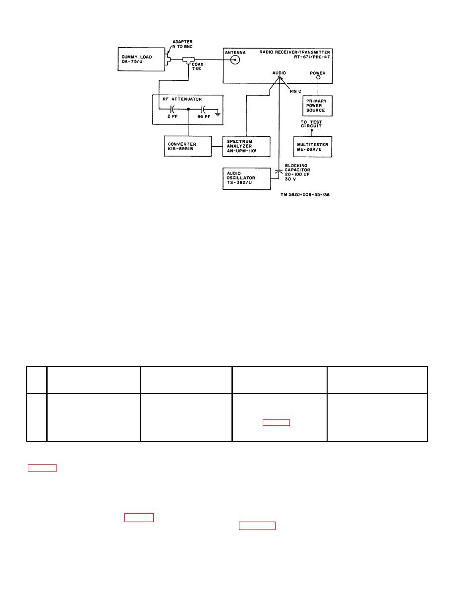
Figure 5-2. Transmitter Hum Balance Adjustment and modulation Fidelity Test, Equipment Setup. |
|
||
| ||||||||||
|
|  TM 11-5820-509-35
Figure 5-2. Transmitter Hum Balance Adjustment and modulation Fidelity Test, Equipment Setup.
LOAD controls on the front of the receiver-
c. Procedure.
transmitter for maximum deflection on the
(1) On the RT-671/PRC-47, set the
XMTR OUTPUT meter. Use the OPR-TUNE
KILOCYCLES indicator to 2400; place the CW-
switch to control power amplifier plate power.
FSK/VOICE switch to VOICE, XMTR PWR switch to LO,
Do not permit the power amplifier to operate
and OPR-TUNE switch to OPR.
for more than a few seconds at a time in the
(2) Place the turns-counters of POWER
unloaded condition, serious equipment
AMPLIFIER TUNE and POWER AMPLIFIER LOAD
damage can result.
controls to the settings recommended on the LOAD-
TUNE chart on the front of the receiver-transmitter.
(3) After resonating the power amplifier plate
CAUTION
circuit at the LO setting of XMTR PWR switch, place the
XMTR PWR switch to HI and peak these controls again.
Before making the following measurements
Immediately return the OPR-TUNE switch to OPR
and adjustments, resonate the POWER
AMPLIFIER TUNE and POWER AMPLIFIER
Test
Radio
equipment
control
Test
Performance
Step
settings
settings
procedures
standards
1
Adjust audio oscillator to
Place CW FSK/VOlCE
Set spectrum analyzer to
Adjust R121 for minimum
2800 Hz and set output
switch to CW-FSK.
2400 kHz and adjust hum
indication at 400 Hz.
level to 0.1 volts.
balance potentiometer
R121 (fig. 3-95).
2
Return CW-FSK/VOICE
switch to VOICE.
5-6. Transmitter Modulation Fidelity Test
(6) Audio Oscillator TS-382/U
(7) Primary power source: 115-volt, 400-Hz,
a. Test Equipment and Material.
single-phase, 3 amp.
(1) Spectrum Analyzer AN/UPM-110
(2) Converter, Hewlett-Packard K15-8551B
b. Test Conditions and Equipment Connections.
(3) Dummy Load DA-75/U
(1) Connect the test equipment to Radio
Receiver-Transmitter RT-671/PRC-47 as shown in
(4) Attenuator (see fig. 5-2)
(5) Multimeter ME-26A/U
do so.
5-3
|
|
Privacy Statement - Press Release - Copyright Information. - Contact Us |
