 |
|||
|
|
|||
|
|
|||
| ||||||||||
|
|  TM 11-5820-509-35
b. Test Conditions and Equipment Connections.
4-11. Receiver Volume Control Test
a. Test Equipment and Material.
(1) Connect the test equipment to Radio
Receiver-Transmitter RT-671/PRC-47 as shown in
(1) Signal Generator SG-103/URM-25F
(2) Frequency Counter AN/URM-79/U.
(2) Connect the primary power source to the
(3) Spectrum Analyzer TS-723A/U.
receiver-transmitter.
(4) Audio load, 300 ohm, 1 watt composition
(3) Turn on the test equipment and place the
resistor.
POWER-LIGHTS switch on RT-671/PRC-47 to POWER
(5) Primary power source: 115-volt, 400 Hz, single-
ON. Permit the equipment to stabilize at least 5
phase, 3 amps. 26.5-volt, dc, 11 amperes approx.
minutes before beginning the procedures shown in chart
below.
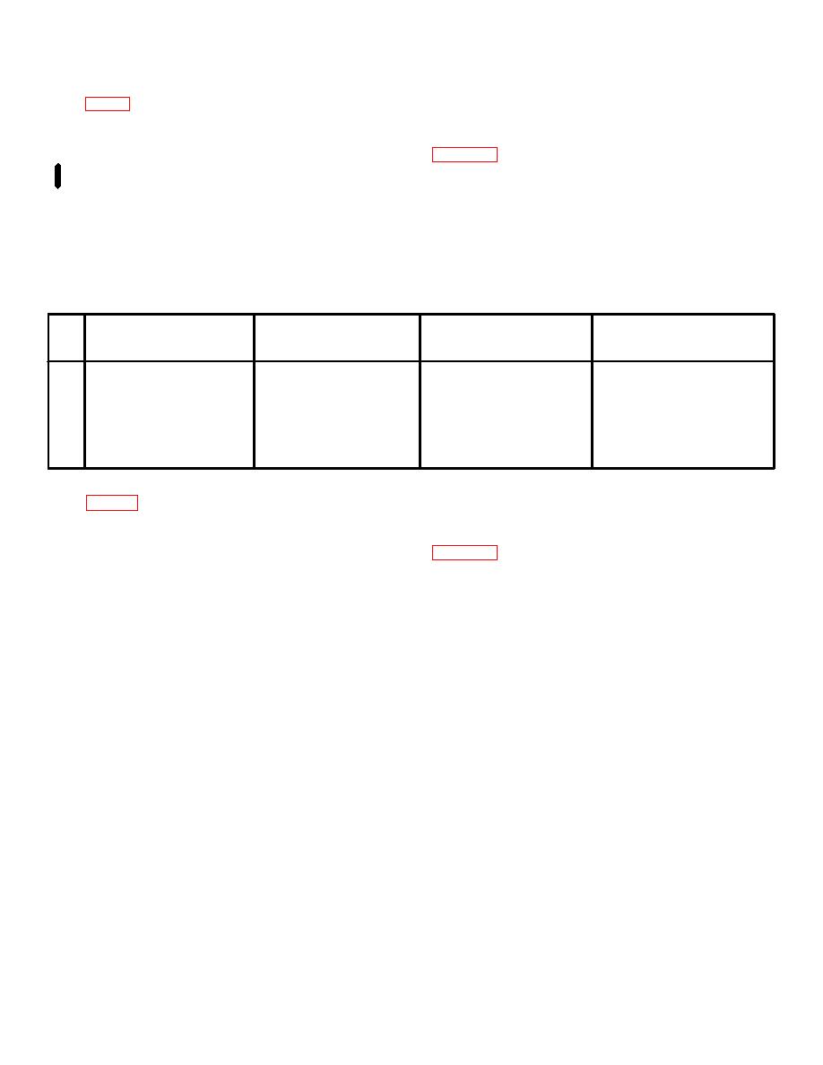
Test
Radio
equipment
control
Test
Performance
Step
settings
settings
procedures
standards
1
Adjust signal generator to 2226
Adjust frequency control knobs
Rotate VOLUME control to
Record audio output voltage across
kHz; set output level to 1000
to 2225 on KILOCYCLES
maximum clockwise stop.
300-ohm audio load.
microvolts.
indicator; CW-FSK/VOICE to
VOICE; OPR-TUNE to OPR.
2
Same as step 1.
Same as step 1.
Rotate VOLUME control to
Record audio output voltage across
maximum counterclockwise
300-audio load. Must be not more
stop.
Than 1/100 of value recorded in
step 1.
b. Test Conditions and Equipment Connections.
4-12. Receiver Audio Output Distortion Test
a. Test Equipment and Material.
(1) Connect the test equipment to Radio
Receiver-Transmitter RT-671/PRC-47 as shown in
(1) Signal Generator SG-103/URM-25F.
(2) Frequency Counter AN/URM-79/U.
(2) Connect the primary power source to the
(3) Distortion Analyzer TS-723/U.
receiver-transmitter.
(4) Audio load, 300 ohm 1-watt composition
(3) Turn on the test equipment and place the
resistor.
POWER-LIGHTS switch on RT-671/PRC-47 to POWER
(5) Primary power source: 115-volt, 400 Hz,
ON. Permit the equipment to stabilize at least 5
single-phase, 3 amps.
26.5-volt, dc, 11 amperes
minutes before beginning the procedures shown in the
approx.
chart below.
Change 1 4-7
|
|
Privacy Statement - Press Release - Copyright Information. - Contact Us |
