 |
|||
|
|
|||
|
Page Title:
Temperature Compensated Oscillator Frequency Adjustment |
|
||
| ||||||||||
|
|  TM 11-5820-509-35
KILOCYCLES indicator to 7000 and set the rotary switch
switch on the antenna simulator to the 11.0 MHz
on the antenna simulator to the 7.0 MHz position.
position.
(11) Adjust A3L72 (fig. 3-96) for maximum rf
(19) Adjust A3L76 (fig. 3-105) for maximum rf
grid drive as indicated by the multimeter connected to
grid drive as indicated by the multimeter connected to
test point J104.
teat point J104.
(12) Repeat
step
b
(2)
except
set
c. Power Amplifier Bias Adjustments.
KILOCYCLES indicator to 8000 and set the rotary switch
NOTE
on the antenna simulator to the 8.0 MHz position.
Perform these adjustments only after
(13) Adjust A3L73 (fig. 3-96) for maximum rf
completing
the
alignment
grid cave as indicated by the multimeter connected to
procedures of step b above.
teat point J104.
(1) Connect the dc probe of the multimeter to
(14) Repeat
step
b
(2)
except
set
the following test jacks on Power Supply PP.
KILOCYCLES indicator to 9000 and set the rotary switch
3518/PRC-47 (A8A5).
on the antenna simulator to the 9.0 MHz position.
(a) At ABJ1 the correct reading is -32
(15) Adjust A3L74 (fig. 3-96) for maximum rf
1 volt; if not, adjust A5R4 as required.
grid drive as indicated by the multimeter connected to
(b) At A5J2 the correct reading is -110
test point J104.
13.3 volts; if not, adjust A5R3 as required.
(16) Repeat
step
b
(2)
except
set
(c) At A5J8 the correct reading is +19
KILOCYCLES indicator to 10000 and set the rotary
0.6 volts; if not, adjust A5R22 as required.
switch on the antenna simulator to the 10.0 MHz
(2) Return the XMTR PWR switch to OFF, the
position.
POWER-LIGHTS switch to POWER OFF, disconnect
(17) Adjust A3L76 (fig. 3-105) for maximum rf
the test equipment, and return the RT-671/PRC-47 to its
grid drive as indicated by the multimeter connected to
case using the procedures of paragraph 3-11 if no
test point J104.
further adjustments are required.
(18) Repeat
step
b
(2)
except
set
KILOCYCLES indicator to 11000 and set the rotary
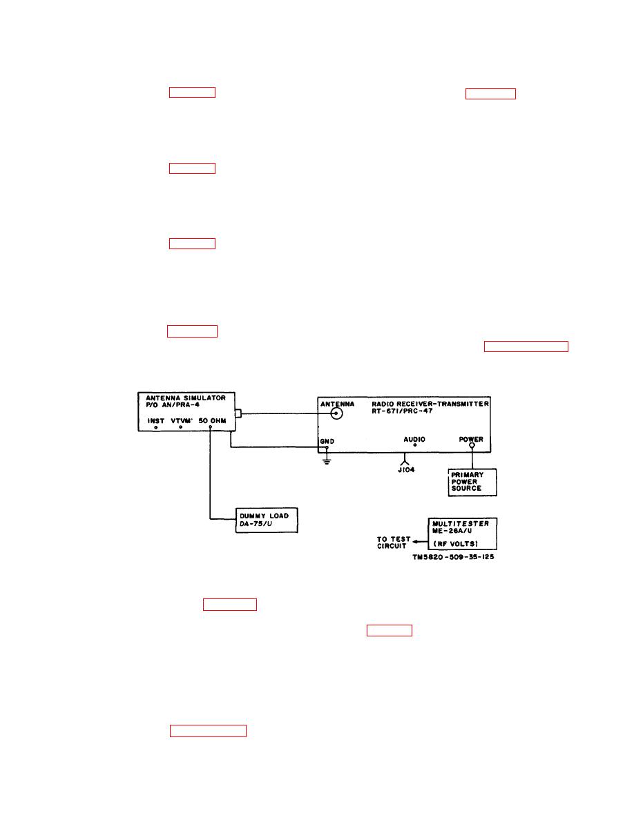
Figure 3-110. Power Amplifier Grid Drive Adjustment, Test Equipment Setup.
3-28.
Temperature
Compensated
(2) Connect the primary power source to the
POWER connector of RT-671/PRC-47.
NOTE
(3) Connect the frequency counter to test jack
Perform this adjustment only if Radio
A6J4 (fig. 3-99) of Radio Frequency Oscillator O-
Frequency Oscillator 0-1032/PRC-47
1032/PRC-47.
(A8A6) has been repaired or
(4) On the front panel of RT-671/PRC-47, set
replaced, or if this module is
the controls as follows:
suspected of generating an incorrect
(a) KILOCYCLES indicator to 2000.
output frequency.
(b) CW-FSK/VOICE switch to VOICE.
a. Preliminary Procedures.
(c) OPR-TUNE switch to OPR.
(1) Remove the RT-671/PRC-47 from its
(d) XMTR PWR switch to OFF.
case using the procedures of paragraph 3-11.
(e) POWER-LIGHTS switch to POWER
3-129
|
|
Privacy Statement - Press Release - Copyright Information. - Contact Us |
