 |
|||
|
|
|||
|
Page Title:
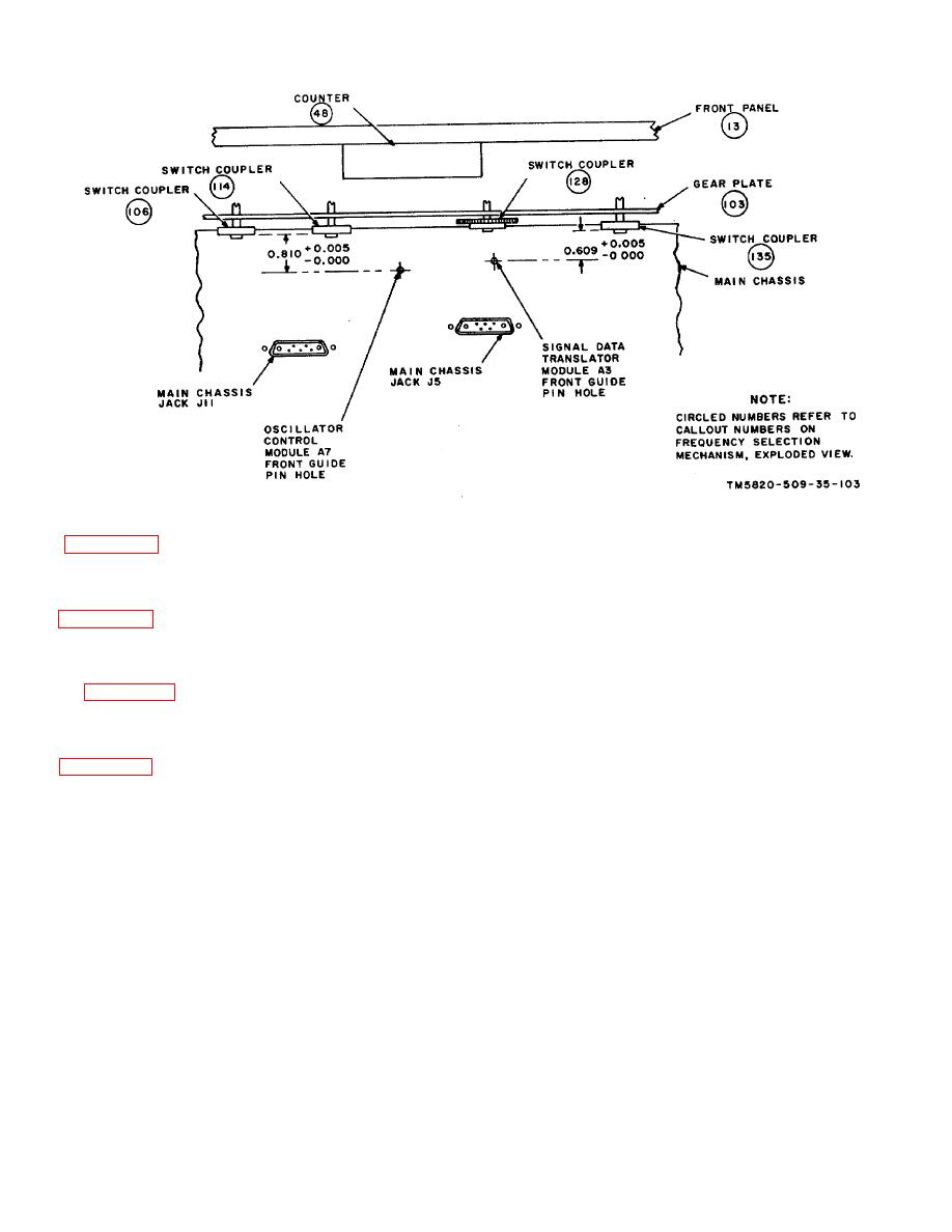
Figure 3-88. Frequency Selector Control, Switch Coupler Alignment Diagram |
|
||
| ||||||||||
|
|  TM 11-5820-509-35
Figure 3-88. Frequency Selector Control, Switch Coupler Alignment Diagram
Figure 3-89. Radio Receiver-Transmitter RT-671/PRC-47, Power Amplifier Compartment (A8A4A) ), Load-Tune
Coil Assembly, Exploded View.
(Located in back of manual.)
Figure 3-90. Radio Receiver-Transmitter RT-671/PRC-47, Frequency Selection Mechanism (A8A4A1 ), Exploded
View.
(Located in back of manual.)
Capacitor Switch, Exploded View.
Located in back of manual.)
Figure 3-92. Radio Receiver-Transmitter RT-671/PRC-47, Power Amplifier Compartment (A8A4A1 ), XMTR PWR
Switch (S103 ), Exploded View.
(Located in back of manual.)
3-94
|
|
Privacy Statement - Press Release - Copyright Information. - Contact Us |
