 |
|||
|
|
|||
|
Page Title:
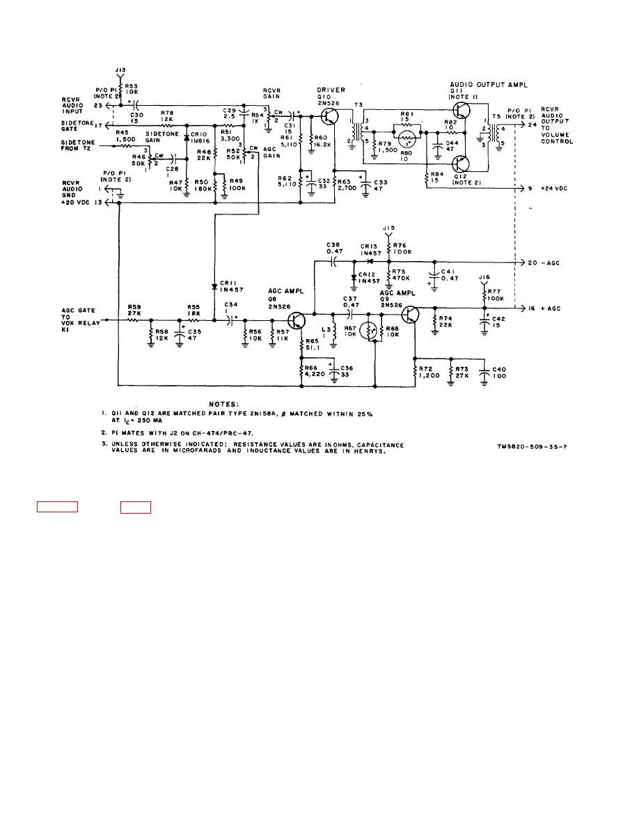
Amplifier-Modulator AM 3507/PRC-47 (A8A2) |
|
||
| ||||||||||
|
|  TM 11-5820-509-35
Figure 2-7. Receiver Amplifier, AGC Circuit, and Sidetone Gate, Schematic Diagram.
and off in parts by the symetrically-fed transmit 500-kHz
2-10. Amplifier-Modulator AM 3507/PRC-47 (A8A2)
standard signal. The output, therefore, consists of a
alternate positive and negative 500kHz pulses that
constitute the double-sideband, suppressed carrier
signal.
This double sideband is routed through
operated and 500-kHz relay K4 (on the main chassis) is
transformer T2 to alc amplifier Q1. The gain of alc
also energized. The transmit 500-kHz standard signal
amplifier Q1 is controlled by the +alc and-alc bias
from radio frequency oscillator A6 is routed through K4
voltages that are returned to it from the power amplifier
to the balanced modulator where it is mixed with the
and this assures that the sideband power level at the
transmit audio output of amplifier A1Q4. The output of
transmitter output is maintained within the capabilities of
balanced modulator CR1 through CR4 is a series of
the power amplifier tube. alc amplifier Q1 is connected
pulses whose polarity and repetition rate are determined
in a common-base configuration and operates normally
by the phase and frequency of the 500-kHz standard
with only self bias. The +alc bias is a-100-volt dc
signal and whose amplitude is proportional to the
reference voltage that is applied to the emitter circuit of
instantaneous amplitude of the audio input signal. In
Q1. The-alc bias is applied to the base of Q1 and is
terms of frequency analysis, the balanced modulator
also-110 volts dc except when the power amplifier stage
output contains both upper- and lower-sideband signals
draws grid current (class AB2).When this occurs, the -
displaced from the 500-kHz intermediate frequency by
alc bias becomes more negative and the circuit
the instantaneous audio modulation frequency. The
gain of Q1 is reduced causing a corresponding reduction
balanced modulator has the familiar diode ring
in the power amplifier driving signal.
configuration and provides a push-pull output. The
diodes of the ring are alternately switched on
2-18
|
|
Privacy Statement - Press Release - Copyright Information. - Contact Us |
