 |
|||
|
|
|||
|
Page Title:
Circuit Continuity and Resistance |
|
||
| ||||||||||
|
|  TM 11-5820-498-35
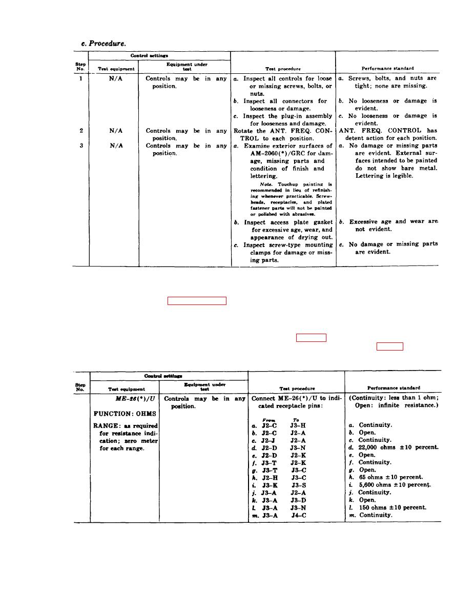
3-19. Circuit Continuity and Resistance
c. Procedure. In the following procedures
The following tests check the circuits that are
"J3-C", "J2-A", etc., indicate the receptacle and
not involved in the tests in paragraphs 3-20, 3-21,
the pins on the receptacle: receptacle J3, pin C;
and 3-22.
receptacle J2, pin A, etc.
a. Test Equipment and Materiel. Multimeter
NOTE
ME-26(*)/U, used as an ohmmeter.
SET POWER receptacle J2 is on the front
b. Test Connections and Conditions. Connect
panel (fig. 3-17) and POWER INPUT recep-
the ME-26(*)/U to the indicated pins on the re-
tacle J3 is on the rear panel (fig. 3-4).
ceptacles given in c below.
3-19
|
|
Privacy Statement - Press Release - Copyright Information. - Contact Us |
