 |
|||
|
|
|||
|
Page Title:
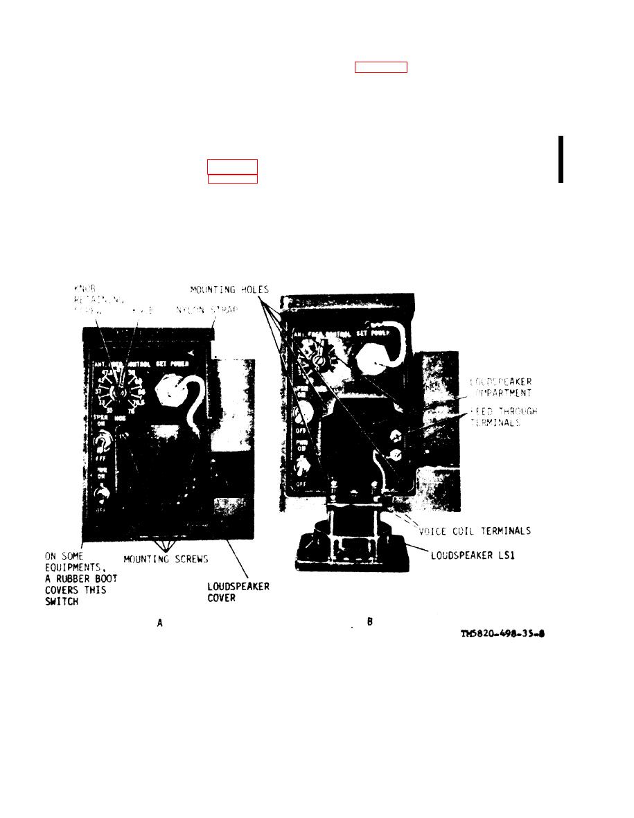
Figure 3-16. AM-2060(*), front panel, parts location. |
|
||
| ||||||||||
|
|  TM 11-5820-498-35
switch to LITE. If the dial map lights, J3 wiring is
10. To facilitate the work, remove the plug-in
incorrect.
assembly (para 3- 13). Perform the operational test
in a above when the rewiring is completed.
switch to ON. If a rushing noise is heard in a
CAUTION
handset connected to the receiver-transmitter, J3
Make sure all changed wires are properly
wiring is incorrect.
taped with electrical insulation tape.
b. Rewiring INPUT POWER Connector J3. If
c. Installation of Zener Diode CR1 in place of
any of the tests performed in a above indicates that
Capacitor C8. If capacitor C8 is defective it will be
J3 wiring is incorrect, rewire the leads at J3 to
replaced by diode CR 1. Remove capacitor C8 and
conform to the circuit shown in figure 4-9. The
install CR1 in its place (fig. 3-16.1).
incorrect wiring at J3 is shown in figure 4-9, note
Figure 3-16. AM-2060(*), front panel, parts location.
Change 3
3-18
|
|
Privacy Statement - Press Release - Copyright Information. - Contact Us |
