 |
|||
|
|
|||
|
Page Title:
AM-2060(*)/GRC, ANT. FREQ. CONTROL Switch S2, Removal and Replacement |
|
||
| ||||||||||
|
|  TM 11-5820-498-35
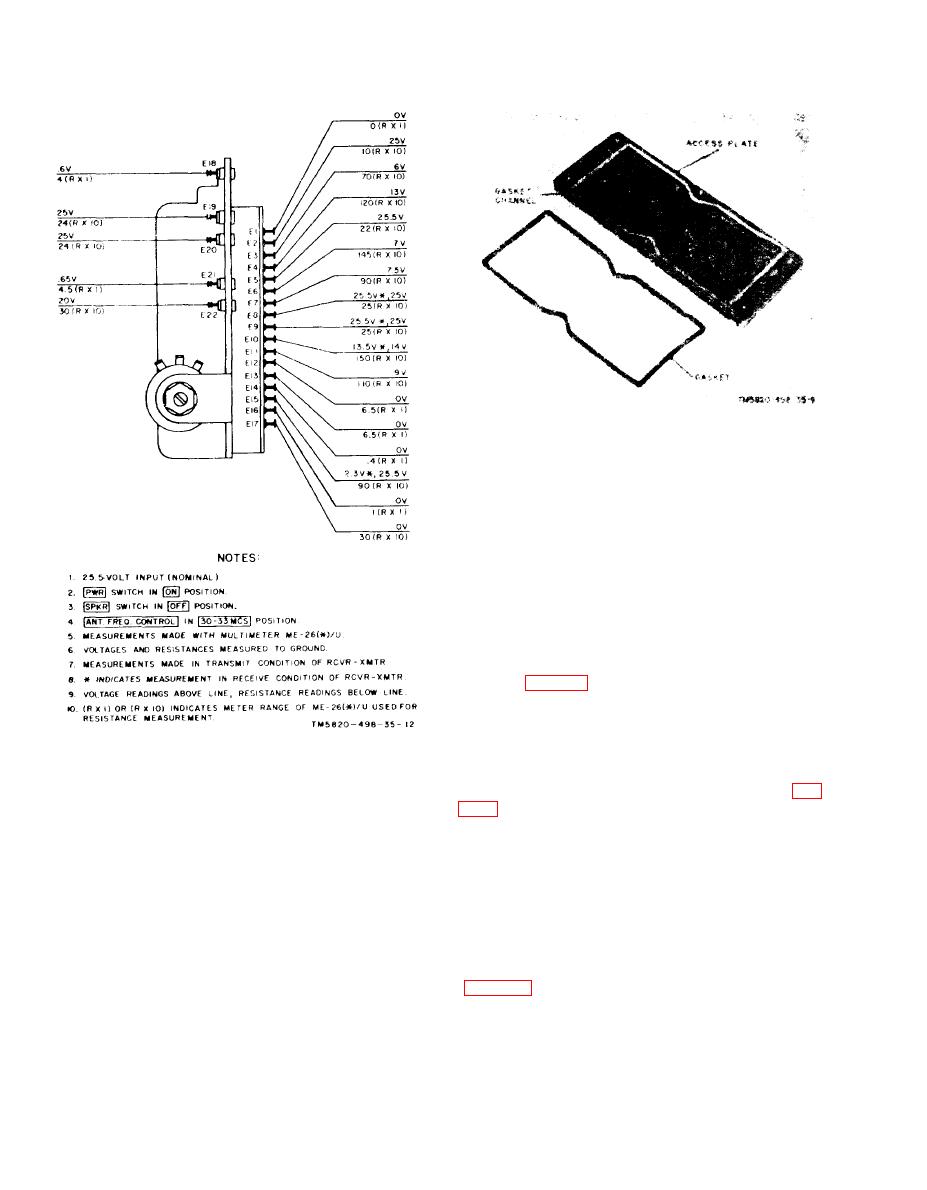
Figure 3-10. AM-2060( * )/GRC, access plate and gasket.
(4) Replace the Mounting screws and nylon
strap.
c. Testing Voice Coil Polarity. When a 4.5
1.5 volt dc potential is connected to the voice
coil terminals, with the positive polarity applied
to the terminal next to the red mark, the voice
coil shall move in a direction away from the mag
net.
315.
AM-2060(*)/GRC, ANT. FREQ.
CONTROL Switch S2, Removal and
Replacement
a. Removal.
( 1 ) Remove the access plate from the top of
the AM- 2060(*)/(GRC.
( 2 ) Set the ANT. FREQ. CONTROL to
Figure 3-9. AM-2060 ( * )/GRC, plug-in assembly, test
3033 position.
points with voltage and resistance indications.
(3) Remove the knob retaining screw (A, fig.
voice coil terminals. Tag the leads (VC1 or VC2)
to insure correct replacement. Remove LS1. See c
shaft.
below for testing the polarity of the loudspeaker
(4) Remove the nut that secures the switch
magnet.
to the front panel.
b. Replacement.
(5) Slide switch S2 back into the compart-
(1) Place the loudspeaker cover on a new
ment. Do not exert too much force or push the
LS1 by holding LS1 firmly and snapping the cover
switch back too far; the leads may break.
i n place. Check to insurc that the mounting holes
(6) Hold the replacement switch in th
in the cover align with the mounting holes in
exact position as the original switch, remove th
LS1.
connecting wires and capacitors C1 through C7
(2) Solder the leads that come from the
feedthrough terminals VC1 and VC2.
time, and connect them to the corresponding con-
(3) Place LS1 in the loudspeaker cavity.
tact on the replacement switch.
Check to insure that the mounting holes in the
b. Replacement.
loudspeaker cover and LS1 align with the mount-
(1) Replace the switch shaft through the
ing holes in the front of the AM- 2060(*) /GRC.
opening in the f ront panel.
3-14
|
|
Privacy Statement - Press Release - Copyright Information. - Contact Us |
