 |
|||
|
|
|||
|
Page Title:
Section II. OA-3633(*)/GRC, TROUBLESHOOTING PROCEDURES |
|
||
| ||||||||||
|
|  TM 11-5820-498-35
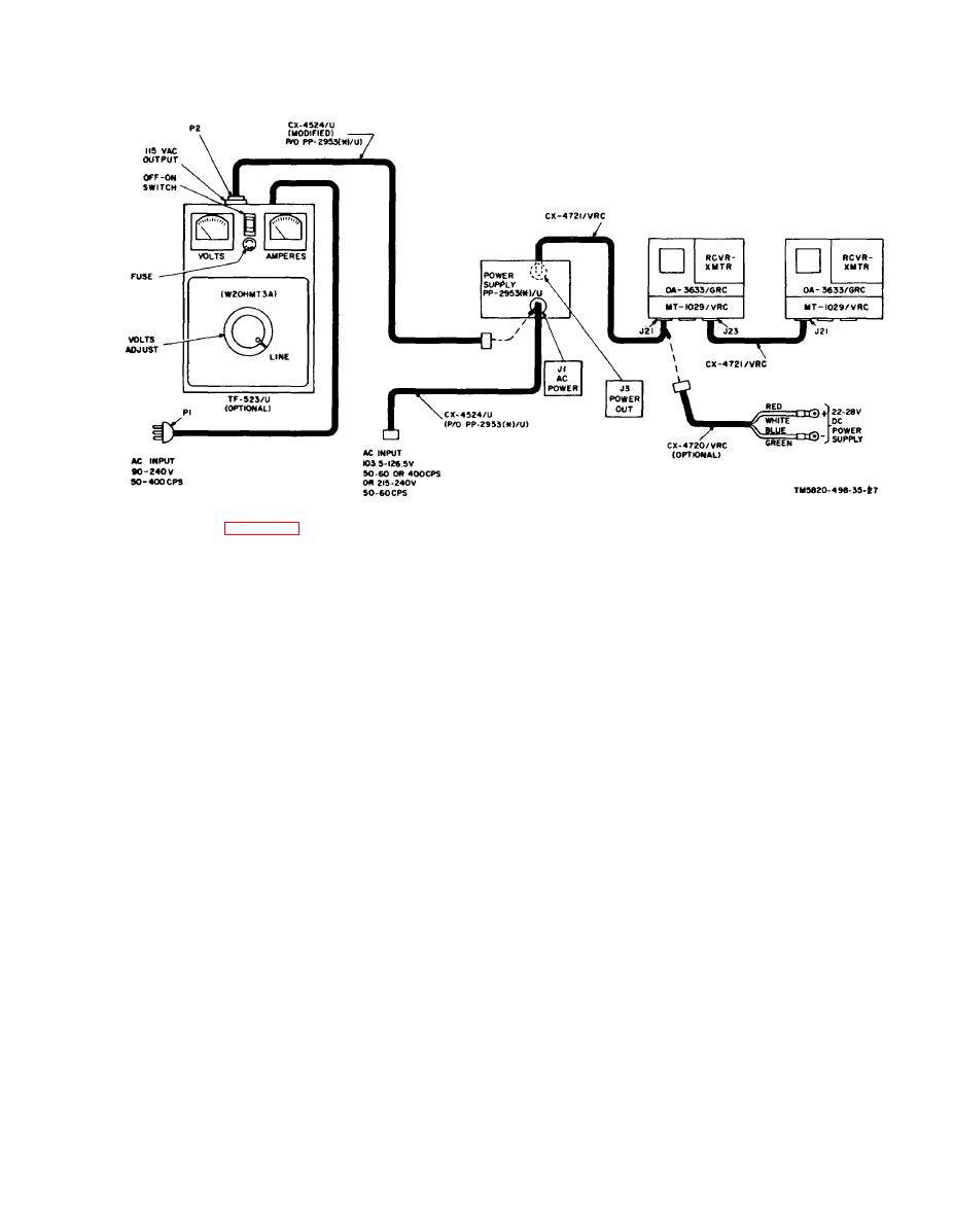
CX-4720/VRC to the male receptacle on the power
distribution box may be connected to another
distribution box (D, fig. 8-4).
piece of equipment using the CX-4721/VRC.
(b) Connect the elliptical receptacle on the
(d) Turn on and adjust the output of the dc
power distribution box to POWER INPUT recep-
power supply to 25.5 volts. Set the PWR switch on
tacle on the rear of the AM-2060(*)/GRC.
the AM2060(*)/GRC to ON when desired.
(c) The female receptacle on the power
Section II. OA-3633(*)/GRC, TROUBLESHOOTING PROCEDURES
than the positive battery terminal and it is con-
3-5. Troubleshooting OA-3633(*)/GRC
a. When the AM2060(*)/GRC resistors R6, R7,
nected to the vehicular chassis by a bonding strap.
and R8 (fig. 3-18) are charred, there will be no
( 2 ) Install Suppressor, Electrical MX-
audio output from the AM2060(*)/GRC tO the
7778/GRC in the battery distribution circuit
receiver-transmitter. These charred resistors usu-
of the vehicle. Installation procedures are pro-
ally indicate that the power cable in the vehicle
vided in TM 115195-223-15, which also covers
( u s u a l l y the CX-4720/VRC) in which the
maintenance o f the suppressor. T h e M X -
AM-2060(*)/GRC had been used, had been con-
7 7 7 8 / G R C protects the vehicle from circuit
nected incorrectly to the vehicular battery. That
overload (short circuit) in the radio (and inter-
is, the CX-4720/VRC negative leads (blue-green)
com) equipment and the radio (and intercom)
had been connected to the battery positive termi-
equipment from electrical transient voltages in
nal, and the positive leads (red-white) had been
the vehicle electrical system.
connected to the battery negative terminal. To
b. When trouble is suspected in the application
prevent incorrect battery connections, the follow-
of operating dc voltages to the receiver-transmit-
ing precautionary procedures are recommended:
ter that was used with the AM-2060(*)/GRC,
(1) Mark the battery terminals of the vehicu-
check the AM2060(*)/GRC output circuits by
lar battery power cable so that the person that re-
performing measurements of the output voltages
places the cable leads to the battery knows the
and resistances at connector J2 (para 38, fig.
positive power cable lead(s) and the negative
3-6).
power cable lead(s). The battery negative termi-
c. When trouble is suspected in the audio ampli-
nal can be identified by the fact that it is smaller
3-5
|
|
Privacy Statement - Press Release - Copyright Information. - Contact Us |
