 |
|||
|
|
|||
|
Page Title:
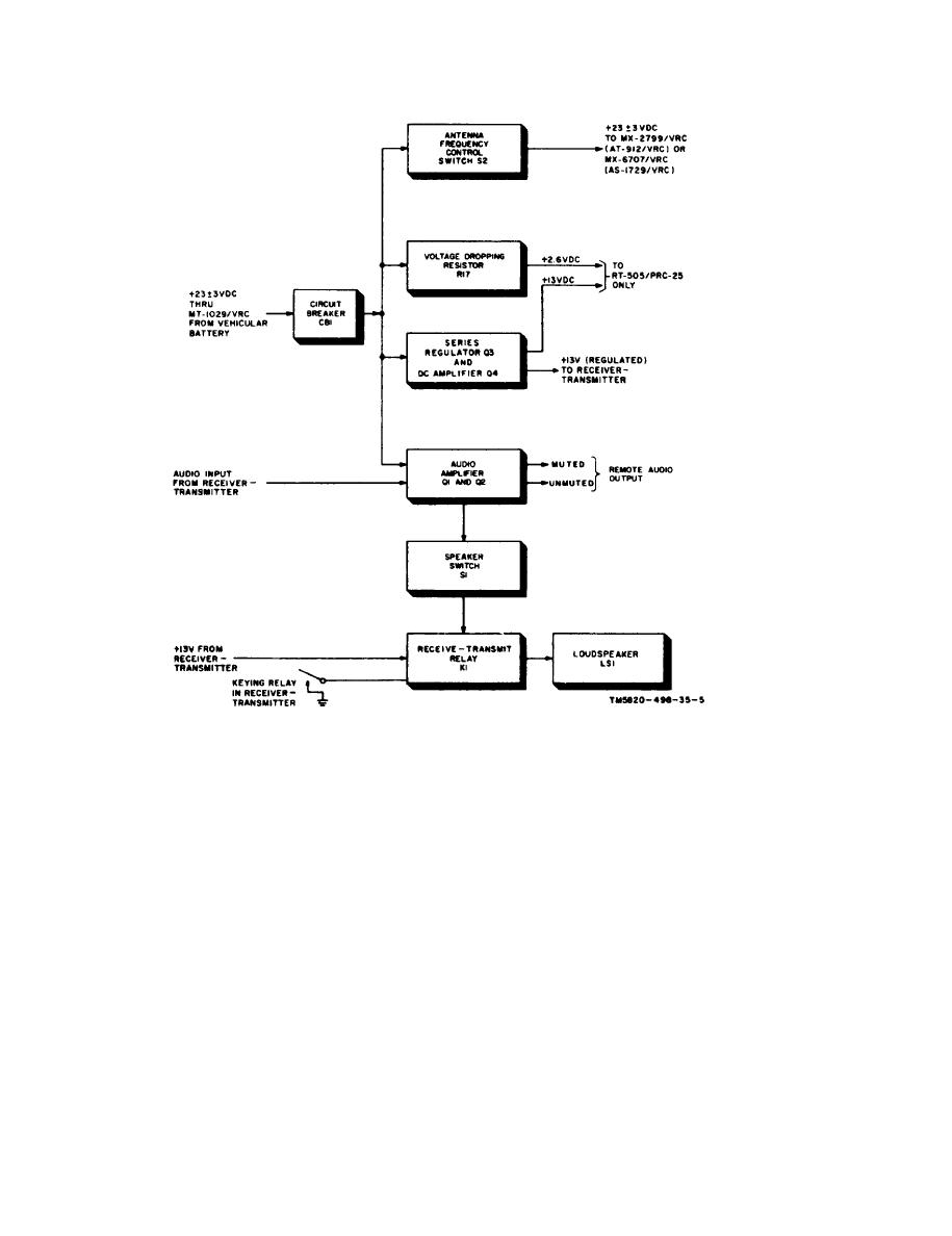
Figure 2-1. Amplifier-Power Supply AM-2060(*)/GRC, block diagram. |
|
||
| ||||||||||
|
|  TM 11-5820-498-35
Figure 2-1. Amplifier-Power Supply AM-2060(*)/GRC, block diagram.
tive temperature coefficient to compensate for
at OFF, resistor R16 acts as the output load for
the audio amplifier through closed contacts 2 and
temperature variations during operation. Resis-
3 of S1. Resistors R14 and R18 provide imped-
tors E1 and R4 provide negative feedback to the
ance matching for the audio accessories at the
base of Q1 and Q2 to control the gain of the am-
plifier. Resistors R7 and R8 prevent current satu-
crewmember control boxes.
b. Series Regulator Q3 and Dc Amplifier Q 4 .
ration of Q1 and Q2.
(3) A +13-volt dc output from the receiver-
Series regulator Q3 and dc amplifier Q4 reduce
the 25.5-volt dc power from the vehicular battery
transmitter is applied to contact 1 of relay K1
through pin N of connector J3. When the re-
to 13 volts and 3 volts dc, and regulates these
voltages. The 13 volts dc is applied to the RT-
ceiver-transmitter is keyed, a ground is applied
505/PRC-25 or RT-841/PRC77; the 3 volts
through pin C of J3 to energize K1. When K1 is
dc is used only by the RT-505/PRC-25.
energized, loudspeaker M1 is disconnected from
the circuit, and a remote muting path (pin D of
(1) The +25.5-volt dc input at pin J or
J3) is grounded through closed contacts 4 and 7.
POWER INPUT connector J3 is applied through
Energizing relay K1 mutes any audio accessory
CB1, bias resistor R5 to the collector of Q3, and
bias resistor R6 to the base of Q3 and the collec-
at the crewmember control boxes. When LS1 is
disconnected from the circuit (K1 energized), re
tor of Q4. The regulated +13 volts that appear:
sisters R12 and R13 act as a load for the second-
across filter capacitor C1 is applied to pin E of
ary of transformer T2. When the SPKR switch is
SET POWER connector J2. The regulated +3
2-12
|
|
Privacy Statement - Press Release - Copyright Information. - Contact Us |
