 |
|||
|
|
|||
|
|
|||
| ||||||||||
|
|  TM 11-5820-401-34-3/0967-LP-432-3060
LOCAL OSCILLATOR A1500 ALTERNATE ALINEMENT PROCEDURE. (CONT)
5-17.
INITIAL EQUIPMENT CONTROL SETTINGS. Change the final settings used in the CRS test as follows:
1. Set R-442/VRC MC-TUNE-KC control to 30.00 MHz.
2. Set AN/USM-207 SENSITIVITY switch as necessary to trigger frequency counter.
ALINEMENT PROCEDURE
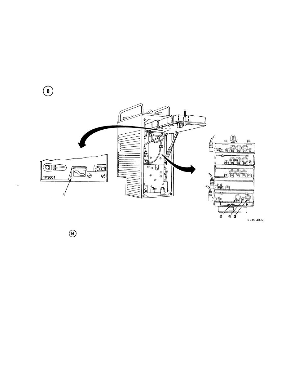
1.Connect M&26(*)/U positive lead to TP3001 (1) and negative lead to ground. (See test setu~
diagram
.)
NOTE
In the following adjustments, it may not be possible to achieve zero-frequency error and
zero-vdc indication on the ME-26(*)/U. Local oscillator tolerance with the CRS con-
nected is 3.5 kHz. The ME-26(*)/U should not exceed 0.5 vdc.
2. Adjust L1502 (2) for 41.5-MHz reading on counter and zero vdc (midscale) on ME-26(*)/U.
3. Set R-442/VRC MC-TUNE-KC control to 52.00 MHz.
4. Adjust L1501 (3) for 63.5-MHz reading on counter and zero vdc (midscale) on ME-26(*)/U.
5 Set R-442/VRC to 42.00 MHz.
6. Adjust C1501 (4) for 53.5-MHz reading on counter and zero vdc (midscale) on ME-26( *)/U.
7. Set R-442/VRC to 30.00 MHz.
8. Repeat steps 2 through 6 until ME-26(*)/U reads zero vdc for all three frequencies.
9. Reconnect P1004 to J1004.
5-97
|
|
Privacy Statement - Press Release - Copyright Information. - Contact Us |
