 |
|||
|
|
|||
|
|
|||
| ||||||||||
|
|  .
TM 5820-401-34-3/0967-LP-432-3060
4-26.
A5200 SQUELCH AMPLIFIER ALINEMENT, OLD SQUELCH LEVEL. (CONT)
ALINEMENT PROCEDURE
Disconnect rf cable from R-442/VRC ANTENNA port.
1.
2.
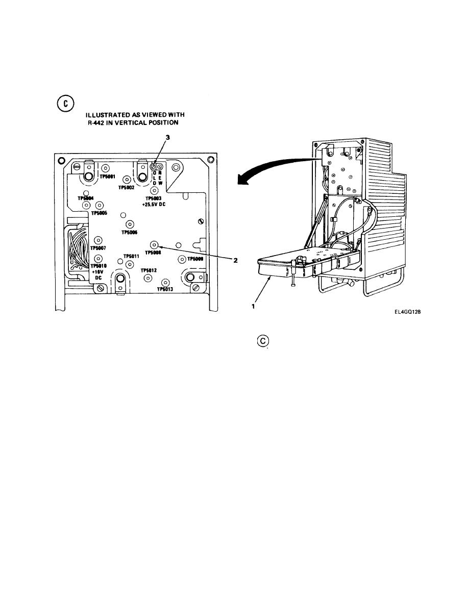
Lift R-442/VRC A3000 tray (1). (See test setup diagram
.)
3.
Connect attenuated probe A to TP5008 (2). Connect alligator clip B to ground.
4.
Note db reading on MM-100E red db scale.
Reconnect rf cable to R-442/VRC ANTENNA port.
5.
6.
Reset AN/GRM-114A MODULATION FREQ Hz thumbwheels to vary modulation frequency 100
Hz while observing MM-100E for voltage peak. Stop at frequency that produces peak voltage
within the 100-HZ limits.
NOTE
If a voltage peak is not seen, it is possible that the modulating signal strength is too high.
Try reducing the deviation by adjusting the VAR control, then repeat step 6. If a peak is
still not clearly observed, leave the MODULATION FREQ Hz set at 07300.0, and go to
step 7.
Adjust VAR (deviation) control for an MM-100E reading 4 db less than that noted in step 4.
7.
Check R-442NRC CALL light. If light is out, go to step 9. If light is on, go to step 10.
8.
CALL LIGHT OUT. Turn R5216 (3) counterclockwise slowly and stop at point where light just
9.
comes on.
CALL LIGHT ON. Turn R5216 (3) clockwise until light goes out, then perform step 9.
10.
4-144
|
|
Privacy Statement - Press Release - Copyright Information. - Contact Us |
