 |
|||
|
|
|||
|
|
|||
| ||||||||||
|
|  TM 11-5820-401-34-3/0967-LP-432-3060
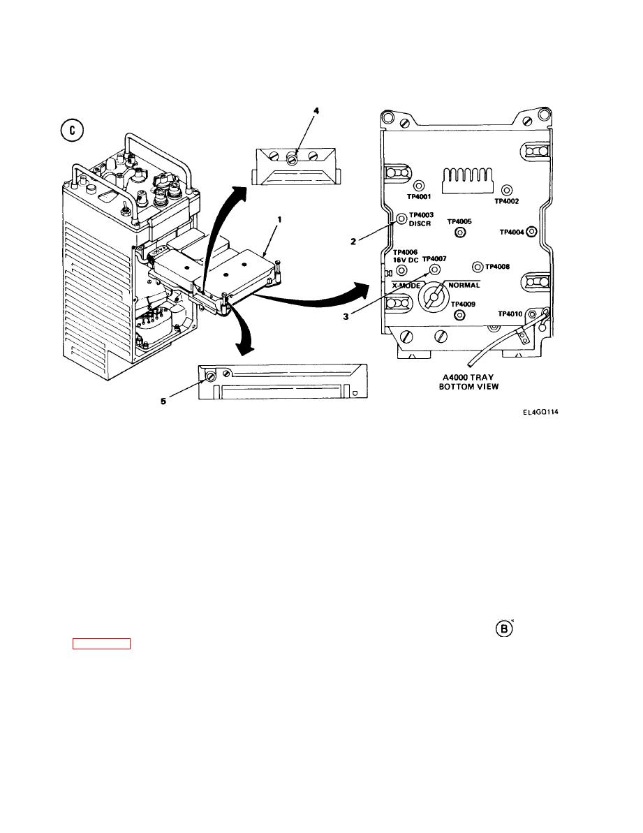
IF DISCRIMINATOR A4200 ALINEMENT. (CONT)
4-18.
ALINEMENT PROCEDURE
Lift A4000 tray (1).
1.
Adjust AN/GRM-114A VERT and HORIZ controls to center scope trace at zero line.
2.
Connect AN/GRM-114A test probe A to TP4003 (2). Connect lead B to ground.
3.
Adjust T4206 (4) to center scope trace on zero line.
4.
Set attenuated probe to x1.
5.
Connect probe A to TP4007 (3).
6.
Adjust T4207 (5) for maximum voltage reading on MM-100E.
7.
Repeat steps 3 through 7 until maximum MM-100E reading and zero-vdc scope trace are
8.
present at same time.
9. Connect probe A to TP4003 (2). Probe must remain on xl setting.
10. Set MM-100E to 01- 10% DIST.
11. Set AN/GRM-114A HI LVL/v x 100/NORM switch to v x 100.
12. Set AN/GRM-114A RF LEVEL control to 2.
13. Adjust T4207 (5) for distortion reading on MM-100E slightly less than 5 percent.
14. If adjustment of T4207 is required in step 13, repeat steps 2 through 7 after first restoring
MM-100E and AN/GRM-114A controls to initial settings given in test setup diagram
,
4-122
|
|
Privacy Statement - Press Release - Copyright Information. - Contact Us |
