 |
|||
|
|
|||
|
|
|||
| ||||||||||
|
|  TM 11-5820-4O1-34-3/0967-LP-432-3060
CRYSTAL REFERENCE SYSTEM (CRS) TEST. (CONT)
4-15.
NOTE
If the tone changes after step 8 is completed, the CRS may be defective. See the
troubleshooting section.
9. Set R-442/VRC MC-TUNE-KC control to 30.50 MHz.
Disconnect rf cable from AN/GRM-114A TRANS-RCVR jack (1). (See test setup
10.
diagram
.)
11. Connect amphenol adapter to TRANS-RCVR jack.
12. Disconnect P1004 from J1004 on A1000 tray. (See test setup diagram C , page 4-111.)
13. Connect P10004 to amphenol adapter at AN/GRM-114A TRANS-RCVR jack .
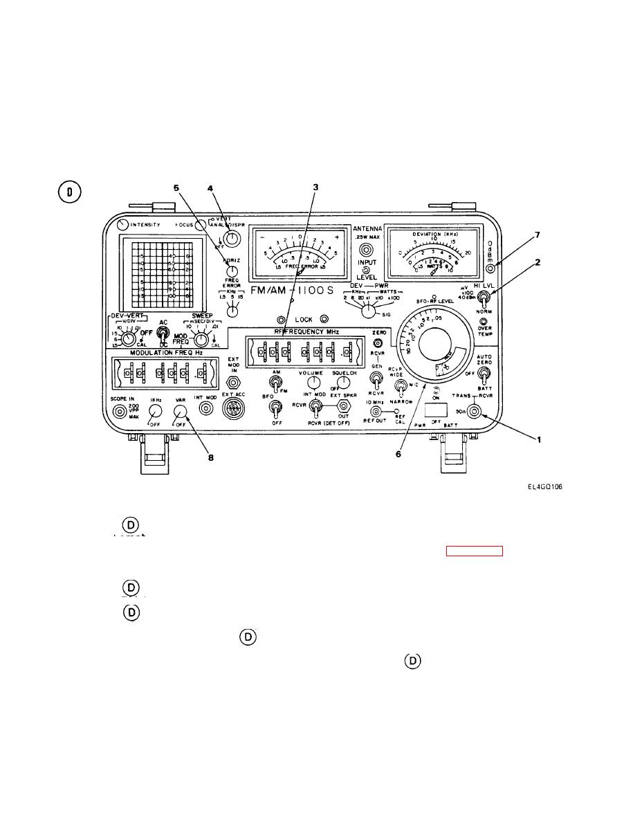
14. Set AN/GRM-114 HI LVL/ v x 100/NORM switch (2) to HI LVL. (See test setup
diagram
.)
15. Set AN/GRM-114A RF FREQUENCY MHz thumbwheels (3) to 0420000. (See test setup
diagram
.)
16. Adjust AN/GRM-114A VERT control (4) and HORIZ control (5) to center scope trace on
screen. (See test setup diagram
.)
17. Turn AN/GRM-114A RF LEVEL control (6) fully counterclockwise; then slowly clockwise
and stop when 0 dbM lamp (7) comes on. (See test setup diagram
.)
4-112
|
|
Privacy Statement - Press Release - Copyright Information. - Contact Us |
