 |
|||
|
|
|||
|
Page Title:
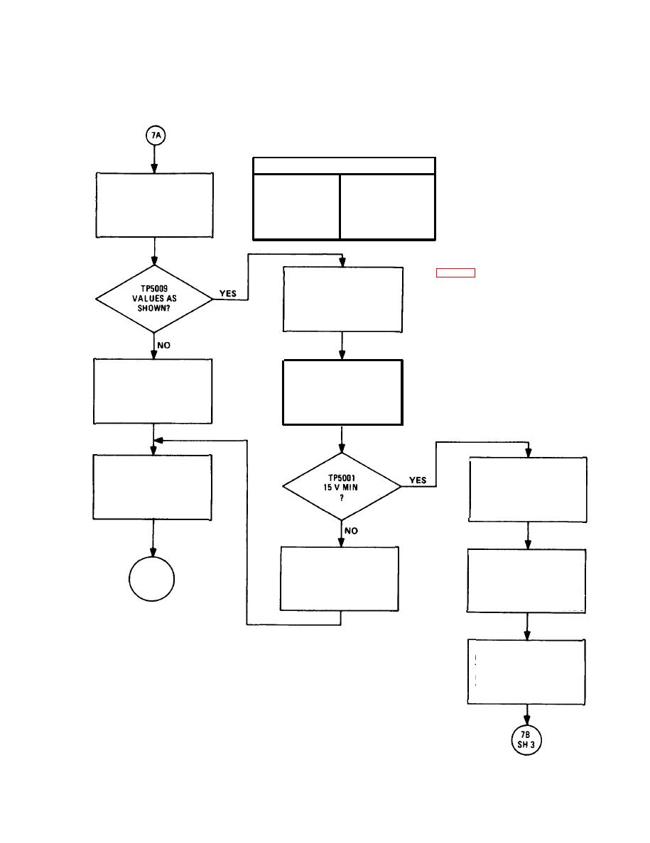
CHART 3-10. A5000 Assembly Troubleshooting (Sheet 2 of 10) |
|
||
| ||||||||||
|
|  TM 11-5820-401-34-3/0967-LP-432-3060
3-13. TROUBLESHOOTING FLOW CHARTS. (CONT)
CHART 3-10
A5000 Assembly Troubleshooting
(Sheet 2 of 10)
TABLE A
TP5009 (DB CHANGE
INJECT 3.0 V INTO X-MODE
X-MODE RCVR (HZ)
FROM 1 KHZ VALUE)
AUX RCVR CONNECTOR AT
FREQ'S IN TABLE A. NOTE
300
1.0
DB CHANGES AT TP5009.
3000
1.0
6000
-21 MIN
NOTES
4. See chapter 2, section Ill, Maintenance
Procedures.
INJECT 0.775 VAT 1 KHZ.
TURN R-442/VRC VOLUME
5. FUNCTION EXT MOD set AN/URM-127 for
CONTROL FULLY
1 kHz at 10 V.
CLOCKWISE.
CONNECT ME-30/U LEAD A TO
REPLACE AND A LINE FL5001
TP5001. (SEE SH 9.)
POWER OFF. CONNECT
RETURN TO PERFORMANCE
EQUIPMENT AS SHOWN ON
TESTS
SH 9. POWER ON.
ADJUST AN/U RM-103 RF
CHECK A5100A, 0201 AND
TUNING CONTROL FOR
PARA
R202. REPLACE IF
60.05 MHZ AND DEVIATION
3-2
NECESSARY.
CONTROL FOR 8 KHZ
SEE NOTE 4
SEE NOTE 5
CONNECT ME-30/U LEAD A
TO TP5004. (SEE SH 9.)
GROUND LEAD B. NOTE
VOLTAGE.
3-31
|
|
Privacy Statement - Press Release - Copyright Information. - Contact Us |
