 |
|||
|
|
|||
|
Page Title:
Selector Mechanism Disassembly Procedure |
|
||
| ||||||||||
|
| 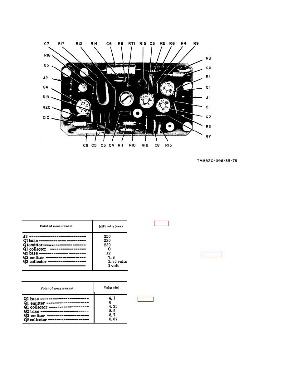 Figure 76. Module A24, parts location.
(3) Measure the voltages at the points
(4) After replacing a faulty part, re-
listed in the charts in (a) and (b)
peat the procedures given in a and
below. Compare them with the nor-
b above.
mal signal and dc voltages listed.
(5) Replace A21.
Note: Make all voltages to ground.
(a) Signal voltage chart.
Procedure
Disassemble the gear train only to the
degree required to remove the defective
part.
a. Remove the selector mechanism from
the receiver-transmitter (para 48).
b. Remove taper pin (48) from arm as-
sembly (49) and remove arm assembly
(49). Remove taper pin (13) from stop (14)
(b) Dc voltage chart.
and remove stop (14).
Note: Setscrews (47) and (15) are not supplied
with the selector mechanism, but are used to se-
cure arm assembly (49) and stop (14) to their re-
spective shafts while drilling replacement parts
c. Disconnect spring (32) from spring
retainer (18) and move arm assembly (33)
away from shaft assembly (30) to facilitate
removal of shaft assembly (30).
|
|
Privacy Statement - Press Release - Copyright Information. - Contact Us |
