 |
|||
|
|
|||
|
Page Title:
Isolating Trouble in Module A25 |
|
||
| ||||||||||
|
|  peat the procedure give n in b
(8) Increase the TS-382F/U frequency
above.
to 160 cps. The ME-26B/U indica-
(4) Replace A21.
tion should remain zero.
(9) Increase the TS-382F/U frequency
to 170 cps. The ME-26B/U inica-
tion should be infinity.
(10) Deere as e the TS-382F/U fre-
a. Preparation.
quency to 140 cps. The ME-26B/U
(1) Prepare the following equipment:
indication should be zero.
(11) D e c r e a s e the TS-382F/U fre-
(b) Voltmeter, Meter ME-30A/U.
quency to 130 cps. The ME -26 B/U
(c) Spectrum Analyzer TS-723A/U.
indication should be infinity.
(d) Handset H-138/U.
c. Faulty Parts Isolation.
(1) Set the TS-382F/U frequency to
(f) Multimeter ME-26B/U.
150 cps and the level to 20 milli-
(2) Remove module A21.
volts at A24J1 pins 1 and 2.
(3) Connect the AN/URM-43A to ANT
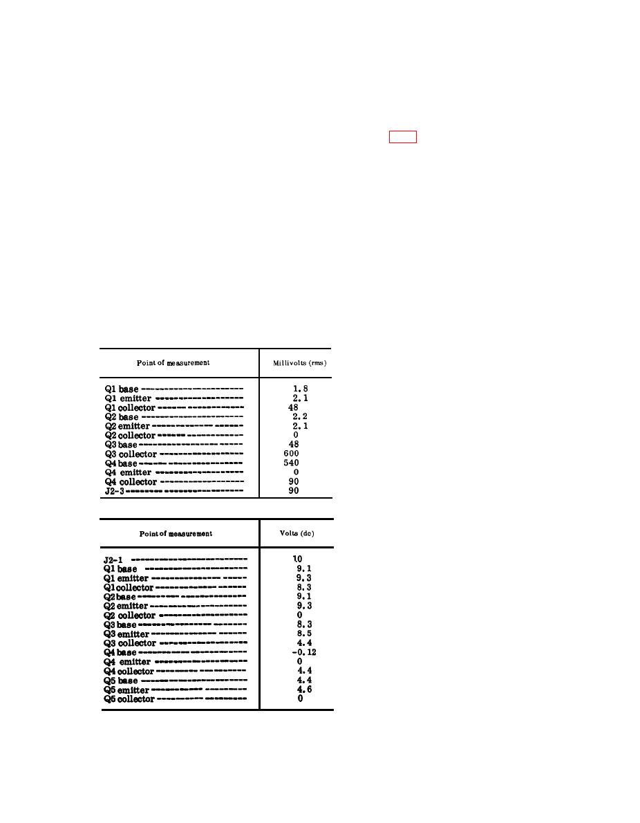
(2) Measure the voltages at the points
connector J2.
listed in the charts in (a) and (b)
(4) Connect the H-138/U to an AUDIO
below. Compare them with the nor-
connector.
mal signal and dc voltages listed.
(5) Set the front panel controls of the
Note: Measure all voltages to ground.
receiver-transmitter as follows:
(a) Signal voltage chart.
(a) BAND switch at 30-52.
(b) Tuning knobs for 30.00 mc.
(c) Function switch at ON.
(6) Connect the TS-382F/U between
A25J3 and ground. Connect the ME-
30A/U across the TS-382F/U out-
put.
(7) Adjust the TS-382F/U frequency
to 1 kc and the level to 0.25 volt
as indicated by the ME-30A/U.
b. Audio Amplifier Distortion and Output
Test.
(1) Connect the ME-30A/U to A25J4
and adjust the front panel VOLUME
(b) DC voltage chart.
control to obtain an ME-30A/U in-
dication of 1 volt. Maintain this
level for each setting.
Note: If the l-volt audio output level
cannot be obtained, proceed to c below.
(2) Connect the TS-723A/U to A25J4,
and measure the audio distortion.
Repeat the procedure above for
300 cps, 2 kc, and 3 kc. The normal
result should be less than 3 percent
for each setting.
c. Faulty Part Isolation.
(1) Set the TS-382F/U to 1 kc, and ad-
just its output for a 0.25 -volt-rms
indication on the ME-30A/U at
A25J3.
(2) Adjust the VOLUME control for a
1-volt rms signal at A25J4.
(3) After replacing a faulty part, re-
|
|
Privacy Statement - Press Release - Copyright Information. - Contact Us |
