 |
|||
|
|
|||
|
Page Title:
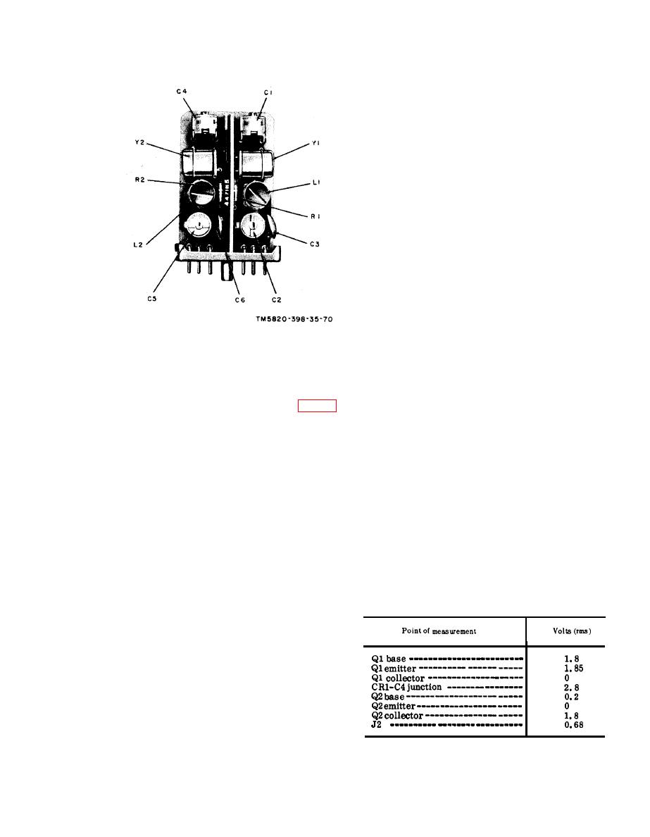
Figure 71. Module A19, parts location |
|
||
| ||||||||||
|
|  ground. Connect the ME-30A/U
across the TS-382F/U output.
(2) Adjust the TS-382F/U frequency to
1 kc and the level to 1.4 millivolts,
as indicated by the ME-30A/U.
(3) Connect the ME-57/U to A20J2.
(4) Press the push-to-talk switch and
repeat the procedure given in (2)
above.
(5) The ME-57/U should indicate a
deviation of 10 kc 2.
(6) Release the push-to-talk switch.
(7) If the deviation given in (5) above
is not obtained, proceed to ebelow.
d. Alignment Procedures.
(1) T - u r n the receiver-transmitter
BAND switch to 30-52.
(2) Press the push-to-talk switch.
(3) Connect the AN/USM-26 and the
411A between A20J2 and chassis
ground; adjust T1 for 11.451 mc
500 cps.
(4) Adjust T2 for a peak indication on
Figure 71. Module A19, parts location.
the 411A.
(5) Release the push-to-talk switch.
(6) If the indications given in (3) and
(4) are not obtained, proceed to e
Place the alignment cover (fig. 28)
below. If they are obtained, repeat
on A20.
c above.
(3) Insert themoduleextender into J16
e. Faulty Part Isolation.
(receptacle for A20). Insert A20
(1) Press the push-to-talk switch.
into the module extender.
(2) Set the TS-382F/U frequency to 1
(4) Connect the AN/URM-43A to ANT
kc and the level to 1.4 millivolts.
connector J2.
Connect TS-382F/U between pin
b. Frequency Accuracy Test.
D of an AUDIO connector and
(1) Set
the
receiver-transmitter
ground.
BAND switch at 30-52, and the
(3) Measure the voltages at the points
function switch at ON.
listed in the charts in (a) and (b)
(2) Connect the 411A and the AN/USM-
below. Compare them with the
26 to A20J2.
n o r m a l signal and dc voltages
(3) Press the push-to-talk switch.
listed.
(4) The AN/USM-26 should indicate
Note: Measure all voltages to ground.
11.451 mc 500 cps, and the 411A
(a) Signal voltage chart.
should indicate 0.68 volt rms.
(5) Turn the BAND switch to 53-75.
The AN/USM-26 should indicate
11.551 mc 500 cps, and the 411A
should indicate 0.68 volt rms.
(6) If the frequencies given in (4) and
(5) above cannot be obtained, pro-
ceed to d below.
c. Frequency Deviation Test.
(1) Connect the TS-382F/U between
pin D of an AUDIO connector and
137
|
|
Privacy Statement - Press Release - Copyright Information. - Contact Us |
