 |
|||
|
|
|||
|
Page Title:
Isolating Troubles in Module A19 |
|
||
| ||||||||||
|
| 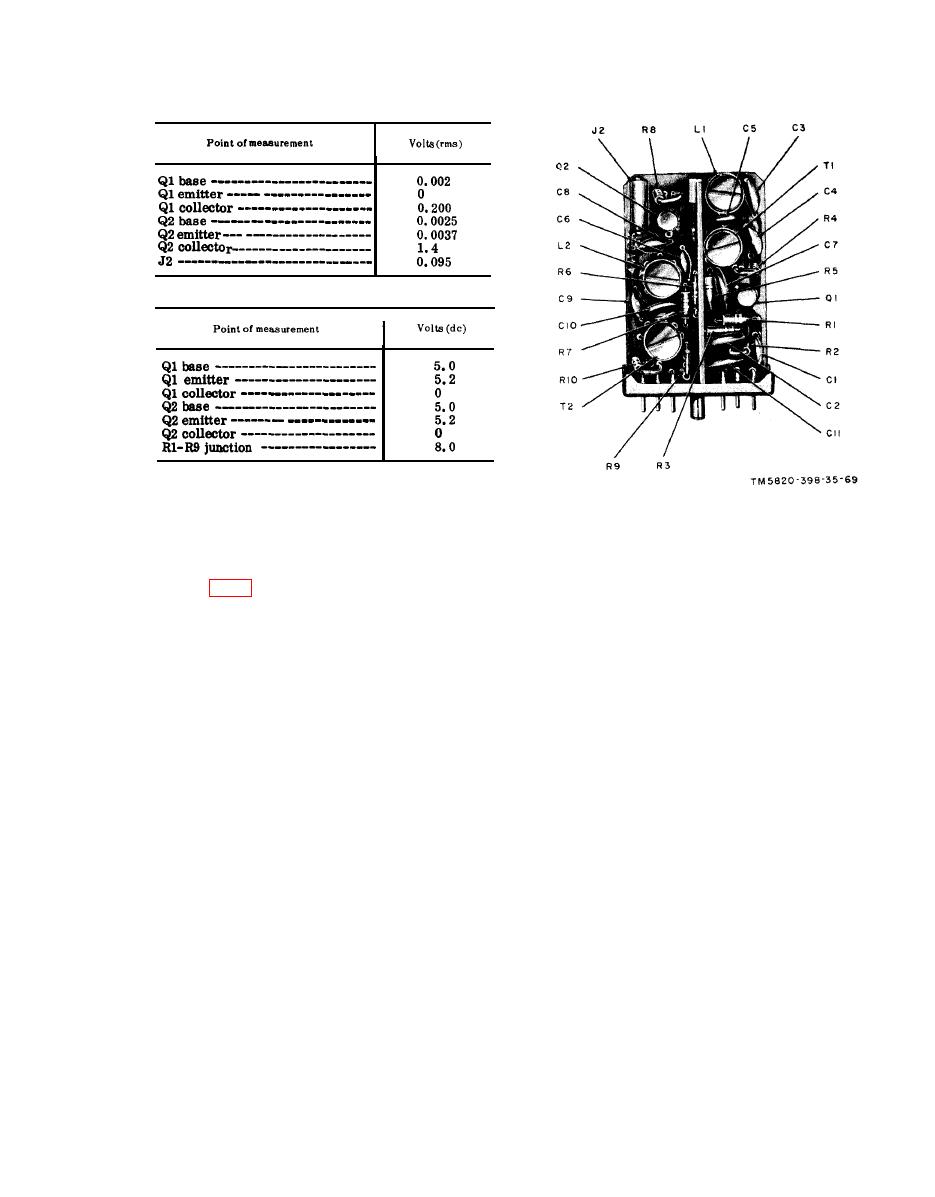 (a) Signal voltage chart.
(b) Dc voltage chart.
(3) After replacing a faulty part, re-
peat all procedures given above.
(4) Replace modules A10 and A12.
Remove the module extender.
Figure 70. Module A18, parts location.
(3) Connect the 411A to A20J2.
(4) Depress and hold the push-to-talk
switch. Observe the 411A and the
a. Preparation.
AN/USM-26.
(1) Prepare the following equipment:
(5) The output level, indicated by the
411A, should be 650 millivolts.
(b) Frequency Meter AN/USM-26.
(6) The output frequency, indicated by
(c) Meter, Modulation ME-57/U.
the AN/USM-26, should be 11.4485
mc 300 cps.
(e) Spectrum Analyzer TS-723A/U.
(7) Release the push-to-talk switch.
(8) Disconnect the AN/USM-26 from
(g) Oscilloscope AN/USM-50A.
A20J2. Connect the ME-57/U be-
tween A20J2 and chassis ground.
(i) Adapter UG-274B/U.
(9) Press the push-to-talk switch. Ob-
serve the indication on the ME-57/
(k) Module extender.
(2) Remove A19.
U . Deviation indicated by the
(3) Insert themodule extender into J15
ME-57/U should be 3 kc 0.5 kc.
(receptacle for A19) and insert A19
Release the push-to-talk switch.
into the module extender.
(lo) Change the receiver-transmitter
(4) Connect the AN/URM-43A to ANT
BAND switch from 30-52 to 53-75.
connector J2.
(11) Press the push-to-talk switch and
observe the 411A and the ME-57/U.
b. Level and Frequency Test.
(1) Connect the AN/USM-26 between
(12) The 411A should indicate 650 mil-
livolts; the ME-57/U should indi-
A20J2 and chassis ground.
cate a deviation of 3 kc +0.5.
(2) T u r n the receiver-transmitter
(13) Release the push-to-talk switch.
function switch at ON, and set the
BAND switch at 30-52.
(14) D i s c o n n e c t the ME-57/U from
|
|
Privacy Statement - Press Release - Copyright Information. - Contact Us |
