 |
|||
|
|
|||
|
Page Title:
Isolating Troubles in Module A18 |
|
||
| ||||||||||
|
|  the AN/USM-50A (connected to pin
F of A17J1) .
(c) Oscilloscope AN/USM-50A.
(3) Repeat the procedures given in b
above.
25F.
d. Faulty Part Isolation.
(1) Set the AN/URM-25F frequency to
(f) Module extender.
5.6 mc, and the level to 0.1 volt
(2) Insert the module extender into J13
rms at A18J2.
(receptacle for A17). Insert A17
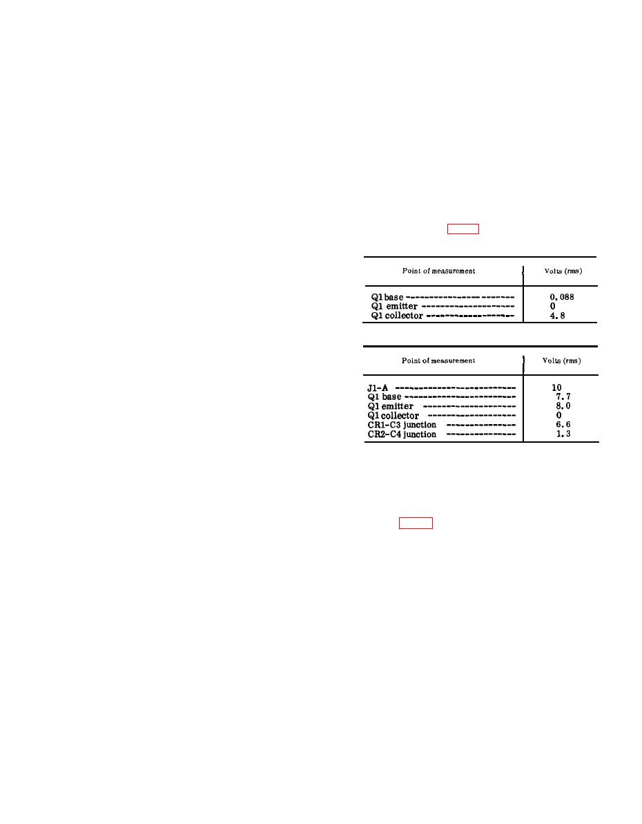
(2) Measure the voltages at the points
into the module extender.
listed in the charts below. Compare
(3) Set the AN/URM-25F output signal
them with the normal signal and dc
frequency to 5.6 mc.
voltages listed.
(4) Connect the AN/URM-25F between
A18J2 and chassis ground.
Note: Measure all voltages to ground,
with S2 (fig. 31) pressed during th. test.
(5) Connect the 411A between pin B of
(a) Signal voltage chart.
A17J1 and ground.
(6) Connect the ME-26B/U between
pin F of A17J1 and ground.
(7) Set the receiver-transmitter func-
tion switch to ON, and the tuning
knobs to 30.05 mc.
(8) Remove module A12.
b. Bandwidth Test,
(b) DC voltage chart.
(1) Adjust the AN/URM-25F for a 0.2-
volt rms indication on the 411A.
(2) Note the voltage at pin F of A17J1,
indicated by the ME-26B/U. Nor-
mal voltage indication is 3.8 volts
dc.
(3) Connect the AN/USM-26 across the
AN/URM-25F output and adjust the
AN/URM-25F frequency to 5.6000
mc as indicated by the AN/USM-
(3) After replacing a faulty part, re-
26.
peat the procedures given in b and
(4) Connect the AN/USM-50A to A17J2.
c above.
(5) Connect the 411A across the AN/
URM-25F output.
(6) Adjust the AN/URM-25F signal
level to 0.1 volt as indicated by the
a. Preparation.
411A and note the indication ob-
tained on the AN/USM-50A.
(1) Prepare the following equipment:
(7) The normal peak-to-peak indica-
tion displayed on the AN/USM-50A
(b) Frequency Meter AN/USM-26.
should exceed 4.5 volts.
(8) If the test results are not normal,
25F.
proceed to c below. (Do not disturb
(d) Multimeter ME-26B/U.
the test equipment settings.)
(e) Module extender.
c. Alignment.
(2) Remove modules A10, A12, and
(1) Disconnect the 411A from the AN/
A18.
(3) Insert the module extender into J14
URM-25F. Use the 411A to meas-
ure signal level between A10J3 and
(receptacle for A18) and insert A18
into the module extender.
chassis ground. A normal indica-
(4) T u r n the receiver-transmitter
tion is 1.8 volts rms.
(2) Adjust T1 for a peak indication on
function switch to ON.
|
|
Privacy Statement - Press Release - Copyright Information. - Contact Us |
