 |
|||
|
|
|||
|
Page Title:
Figure 62. Module A10, parts location. |
|
||
| ||||||||||
|
| 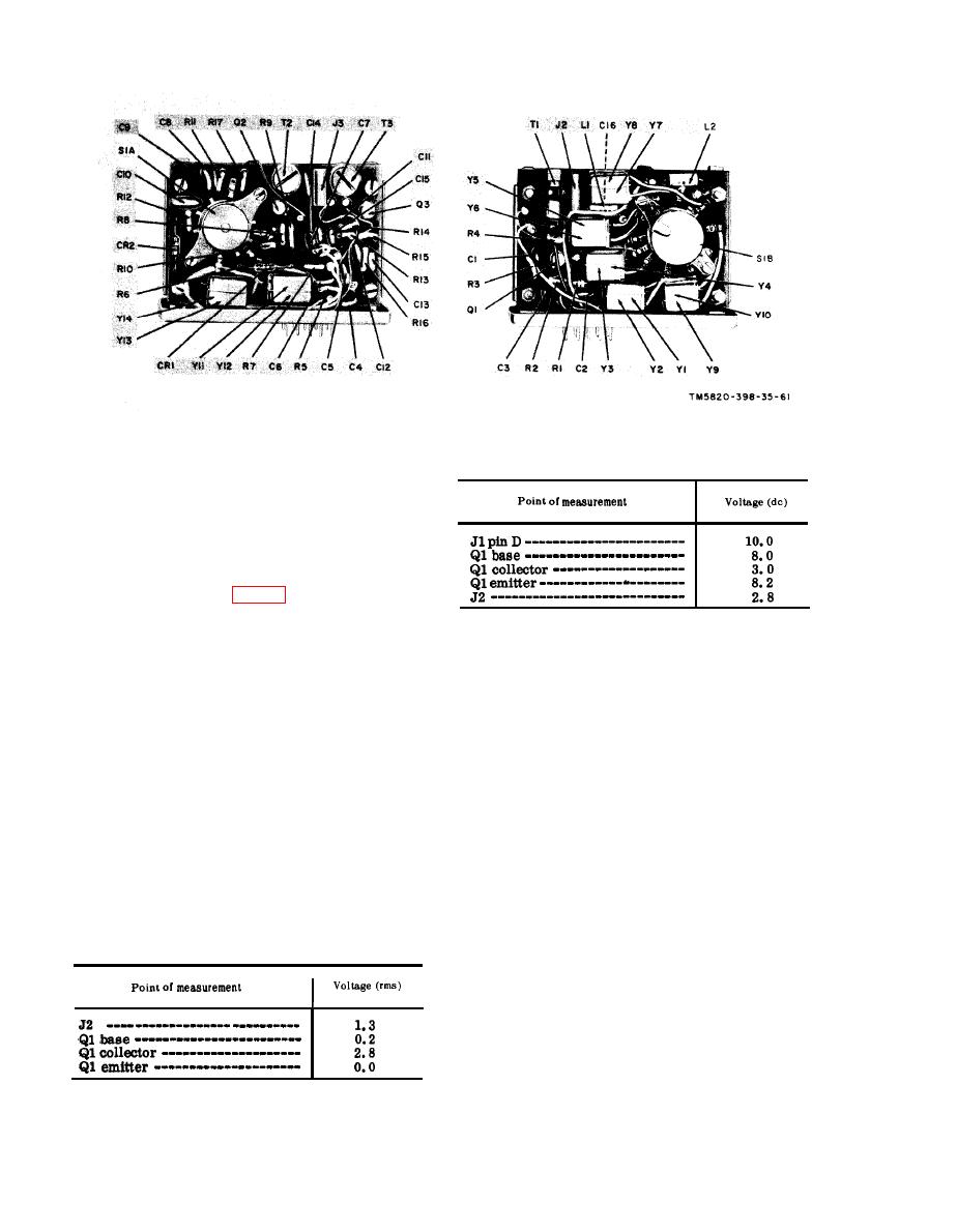 Figure 62. Module A10, parts location.
(3) Turn the receiver-transmitter
(b) DC voltage chart.
function switch to ON.
b. Dc output Level Test.
(1) Connect the AN/URM-48 between
A18J2 and chassis ground. Connect
t h e AN/USM-26 and the 411A
across the AN/URM-48 output.
(2) Press S2 (fig. 31) and adjust the
AN/URM-48 frequency to the level
(2) After the replacement of a faulty
to 0.2-volt as indicated by the 411A.
part, perform the alignment pro-
(3) Disconnect the 411A from the AN/
cedure given in d and e below and
URM-48 and connect it between pin
repeat the procedures given in a
F of A11J1 and ground.
and b above.
(4) Connect the ME-26B/U between
(3) Replace module A12.
A11J2 and chassis ground. The
d. Preparation for Alignment.
ME-26B/U should indicate +2.8
(1) Set the receiver-transmitter front
volts dc.
panel controls as follows:
c. Faulty Parts Isolation.
(a) BAND switch at 30-52.
(1) Apply a 5.6-mc, 0.2-volt signal
(b) Tuning knobs to 30.00 mc.
between A18J2 and chassis ground.
(c) Function switch at ON.
Measure the voltages at the points
(2) Remove A11. Insert the module
outlined in the charts in a a n d
extender into the receptacle for
b below. Compare them with the
A11. Plug A11 into the module ex-
normal signal and dc voltages
tender. Remove module A12.
listed.
(3) Connect the output of the AN/URM-
Note: Measure all voltages to g r o u n d .
(a) Signal voltage chart.
48 to A18J2. Connect the 411A
across the AN/URM-48 output.
(4) Set the AN/URM-48 output to 6.10
mc and adjust the output level to
0.2 volt as indicated by the 411A.
e. Alignment Procedure.
(1) Connect the ME-26B/U between
A11J2 and chassis ground.
126
|
|
Privacy Statement - Press Release - Copyright Information. - Contact Us |
