 |
|||
|
|
|||
|
|
|||
| ||||||||||
|
|  (22) If the gain and bandwidth do not
to 30.00 mc and the level to 100
millivolts, as indicated by the
meet the standards of the proce-
411A.
dure, proceed to c below.
(4)
Disconnect the 411A from the AN/
c. Faulty Parts Isolation.
(1) Remove module A9. Connect the H-
URM-48 and connect it between
138/U to an AUDIO connector. Ap-
pins 3 and 4 of J1.
Adjust T2 for a peak indication on
ply a 30.00 mc, 100-millivolt signal
(5)
between pins 1 and 2 of A8J1. Press
the 411A.
(6)
Change the AN/URM-48 frequency
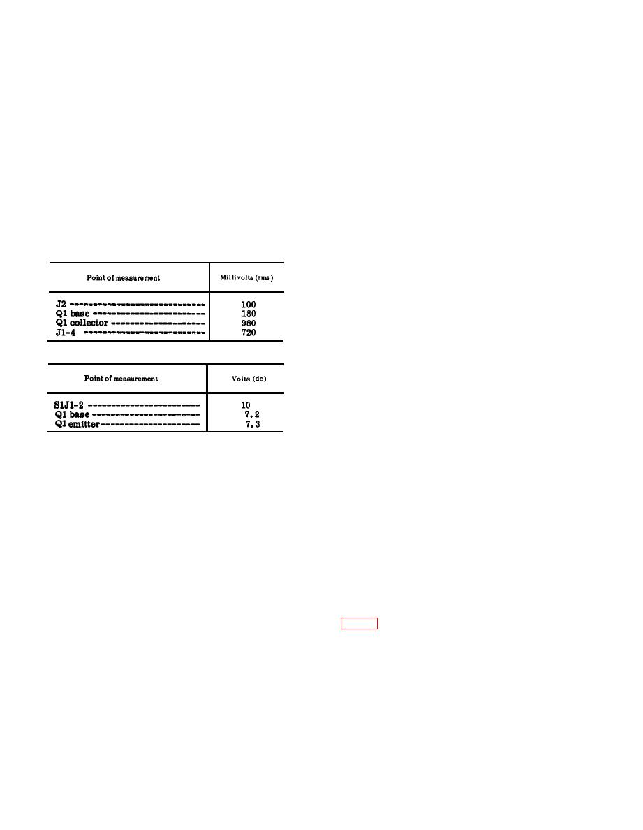
the push-to-talk switch. Measure
and the receiver-transmitter tun-
the voltages at the points given in
ing knobs to 52.95 mc.
the charts in (a) and (b) below.
(7)
Adjust C6 for a peak indication on
Compare them with the normal sig-
nal and dc voltages listed.
the 411A.
Repeat the procedures given in (1)
(8)
Note: Measure all voltages to ground.
through (7) above until the 411A in-
(a) Signal voltage chart.
dication cannot be increased by
tuning.
(9)
Set the BAND s witch on the re-
ceiver-transmitter at 53-75, and
the tuning knobs for 53.00 mc.
(10)
Discomect the 411A from pins 3
and 4 of A8J1 and connect it across
the AN/URM-48 output.
(b) DC voltage chart.
(11)
Adjust the AN/URM-48 frequency
to 53.00 mc and the level to 100
millivolts, as indicated by the
411A.
(12)
Disconnect the 411A from the AN/
URM-48 and connect it between
pins 3 and 4 of A8J1.
(13)
Adjust T3 for a peak indication on
(2) After the replacement of a faulty
the 411A.
part, perform the alignment proce-
(14)
Change the AN/URM-48 frequency
dures outlined in d and e below and
and the receiver-transmitter tun-
repeat a and b above.
ing knobs to 75.95 mc.
d. Preparation for Alignment.
(15)
Adjust C9 for a peak indication on
(1) Set the receiver-transmitter front
the 411A.
panel controls as follows:
(16)
Repeat the procedures given in (9)
(a) BAND switch at 30-52.
through (15) above until the 411A
(b) Function switch at ON.
indication cannot be increased by
(2) Connect the AN/URM-43A to ANT
tuning.
connector J2.
(17)
Replace A9.
(3) Connect the H-138/U to an AUDIO
connector.
(4) Remove module A9.
(5) Connect the AN/URM-48, between
pins 1 and 2 of A8J1.
a. Preparation.
(1) Prepare the foIlowing equipment:
e. Alignment Procedure.
(a) Frequency Meter AN/USM-26.
ing knobs to 30.00 mc.
(2) Connect the 411A across the output
(c) Multimeter ME-26B/U.
of the AN/URM-48. Press the
(d) Hand set H-138/U.
push-to-talk switch.
(2) Connect the AN/USM-26 input to
(3) Adjust the AN/URM-48 frequency
test point A14J2.
|
|
Privacy Statement - Press Release - Copyright Information. - Contact Us |
