 |
|||
|
|
|||
|
|
|||
| ||||||||||
|
|  AN/URM-48 to 53.00 mc instead of
(2) Connect the 411A across the AN/
the indication given in ((6) and (9)
URM-48 output. Press the push-to-
above).
talk switch. Adjust the AN/URM-48
(17) The gain noted in (3) above should
for a 100-millivolt indication on the
be +9.5 db; the 3-db bandwidth com-
411A. (Note the db indication.)
puted in (10) above should be 1,400
(3) Disconnect the 411A from the AN/
kc.
URM-48 and connect it between
pins 3 and 4 of J1. The 411A should
(18) Adjust the AN/URM-48 frequency
to 75.95 mc as indicated by the AN/
indicate 16 db more than the value
indicated in (2) above. (This value,
USM-26. Set the receiver-trans-
+16 db, is the stage gain.)
mitter tuning knobs for the same
frequency.
(4) Adjust the AN/URM-48 level to
(19) Repeat the procedures given in (1)
obtain a 0-db indication on the
411A.
through (10) above; return the AN/
(5) I n c r e a s e the AN/URM-48 fre-
URM-48 to 75.95 mc instead of the
quency until the 411A indicates a
indication given in ((6) and (9)
above).
3-db decrease.
(20) The gain noted in (3) above should
(6) Connect the AN/URM-48 to the AN/
be +10 db; the 3-db bandwidth com-
USM-26 and record the frequency.
puted in (10) above should be 2,800
Decrease the frequency of the AN/
kc.
URM-48 to 30.00 mc.
(21) Replace module A8.
(7) Connect the AN/URM-48 between
(22) If the gain and bandwidth do not
pins 1 and 2 of J1.
meet the standards of the proce-
(8) Decrease the frequency of the AN/
dure, proceed to c below.
URM-48 until the 411A indicates a
3-db decrease.
c. Faulty Parts Isolation.
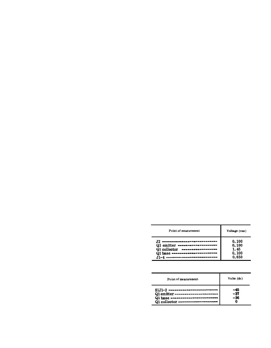
(1) Remove module A8. Connect the H-
(9) Connect the AN/URM-48 to the AN/
138/U to an AUDIO connector.
USM-26 and record the frequency.
Apply a 30.00 mc, 100-millivolt
I n c r e a s e the AN/URM-48 fre-
signal between pins 1 and 2 of A7J1.
quency to 30.00 mc.
P r e s s the push-to-talk switch.
(lo) Compute the difference between the
Measure the voltages at the points
frequencies recorded in (6) and (9)
outlined in the charts in a and b
above. The frequency difference is
below. Compare them with the nor-
the 3-db bandwidth, which should be
mal signal and dc voltages listed.
1,300 kc.
Note: Measure all voltages to ground.
(11) Adjust the AN/URM-48 frequency
to 52.95 mc as indicated by the AN/
(a) Signal voltage chart.
USM-26.
(12) Repeat (1) through (10) above; re-
turn the AN/URM-48 to 52.95 mc
instead of the indication given in
((6) and (9) above).
(13) The gain noted in (3) above should
be +15 db; the 3-db bandwidth com-
puted in the procedure given in (10)
above should be 1,600 kc.
(b) DC voltage chart.
(14) Change the receiver-transmitter
BAND switch to 53-75.
(15) Adjust the AN/URM-48 frequency
to 53.00 mc as indicatedbythe AN/
USM-26.
(16) Repeat the procedures given in (1)
through (10) above, returning the
117
|
|
Privacy Statement - Press Release - Copyright Information. - Contact Us |
