 |
|||
|
|
|||
|
|
|||
| ||||||||||
|
| 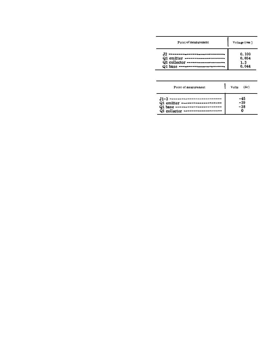 (a) Signal voltage chart.
frequency difference is the 3-db
bandwidth, which should be 1,200
kc.
(11) Adjust the AN/URM-48 frequency
to 52.95 mc as indicated by the AN/
USM-26.
(12) Repeat the procedure given in (1)
through (10) above; return the AN/
URM-48 to 52.95 mc noted in (6)
(b) Dc voltage chart.
and (9) above.
(13) The gain noted in (3) above should
be +21 db; the 3-db bandwidth com-
puted in the procedure given in (10)
above should be 900 kc.
(14) Change the receiver-transmitter
BAND switch to 53-75.
(15) Adjust the AN/URM-48 frequency
to 53.00 mc as indicated by the AN/
(2) After the replacement of a faulty
USM-26.
part, perform the alignment proce-
(16) Repeat the procedure given in (1)
dure given in d and e below and
through (10) above; return the AN/
repeat the procedures given in a
URM-48 to 53.00 mc instead of the
and b above.
indication given in (6) and (9) above.
d. Preparation fbr Alignment.
(17) The gain noted in (3) above should
(1) Set the receiver-transmitter front
be +18 db; the 3-db bandwidth com-
panel controls as follows:
puted in the procedure given in (10)
(a) BAND switch at 30-52.
above should be 1,300 kc.
(b) Function switch at ON.
(18) Adjust the AN/URM-48 frequency
(2) Connect the AN/URM-43A to ANT
to 75.95 mc as indicated by the AN/
connector J2.
(3) Remove module A7.
USM-26 .
(19) Repeat the procedure given in (1)
(4) Connect the AN/URM-48 between
pins 1 and 2 of A6J1.
through (10) above; return the AN/
URM-48 to 75.95 mc instead of the
e. Alignment Procedure.
indication given in (6) and (9) above.
(1) Set the receiver-transmitter tun-
(20) The gain noted in (3) above should
ing knobs for 30.00 mc.
be +12 db; the 3-db bandwidth com-
(2) Connect the 411A across the output
puted in the procedure given in (10)
of the AN/URM-48.
above should be 4,000 kc.
(3) Connect the H-138/U to an AUDIO
(21) Replace module A7.
and press the push-to-talk switch.
(22) If the gain and bandwidth do not
(4) Adjust the AN/URM-48 frequency
meet the outlined standards of the
to 30.00 mc and the level to 100
procedure, proceed to c below.
m i l l i v o l t s , as indicated by the
c. Faulty Parts Isolation.
411A.
(1) Remove module A7. Connect the H-
(5) Disconnect the 411A from the AN/
138/U to an AUDIO connector and
URM-48 and connect it between
press the push-to-talk switch. Ap-
pins 1 and 2 of S1J1.
ply a 30.00 mc, 100-millivolt signal
(6) Adjust T2 for a peak indication on
between pins 1 and 2 of A6J1. Meas-
the 411A,
ure the voltages at the points out-
(7) Change the AN/URM-48 frequency
lined below. Compare them with the
and the receiver-transmitter tun-
n o r m a l signal and dc voltages
ing knobs to 52.95 mc.
listed.
(8) Adjust C6 for a peak indication on
the 411A.
Note: Measure all voltages to ground.
115
|
|
Privacy Statement - Press Release - Copyright Information. - Contact Us |
