 |
|||
|
|
|||
|
Page Title:
Figure 56. Module Ad parts location. |
|
||
| ||||||||||
|
| 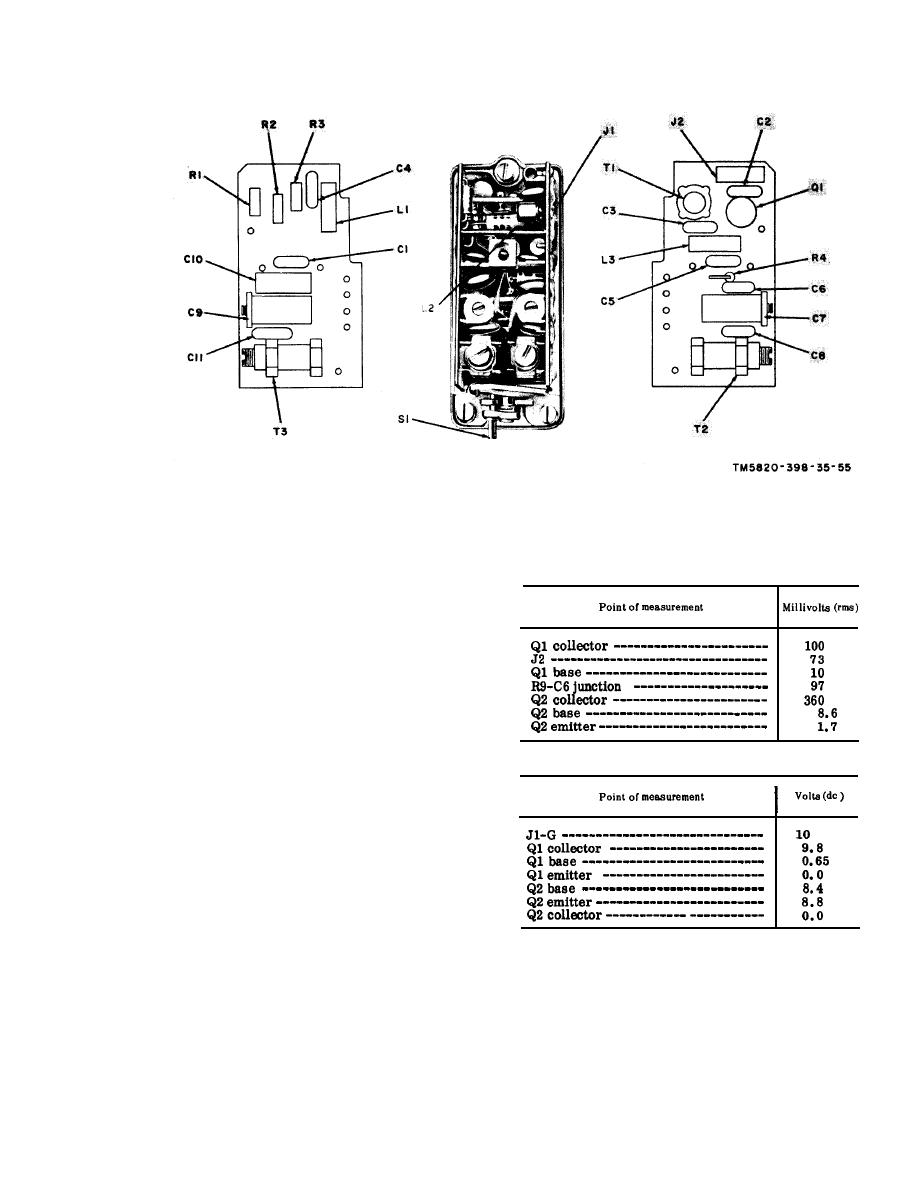 Figure 56. Module Ad parts location.
(9) Increase the AN/URM-48 fre-
(a) Signal voltage chart.
quency until the level indicated by
the 411A is again at the level
noted in (5) above. Record the
(10) Compute the difference between the
frequencies noted in (8) and (9)
above. The frequency difference is
the 6-db bandwidth, which should be
at least 32 kc.
(11) Perform the procedures given in
(b) Dc voltage chart.
(1) through (10) above for 75.95 mc,
except that normal gain in (4) above
is 0 db.
(12) If either the gain or bandwidth tests
or both do not meet the outlined
standards of the procedure, pro-
ceed to e and f below.
c. Faulty Parts Isolation.
(1) Apply a 30.00-mc, 10-millivolt
signal to the module under test.
(2) After the replacement of a faulty
Measure the voltages at the points
part, perform the alignment pro-
outlined below. Compare them with
cedure given in d and e below and
the normal signal and dc voltages
repeat the procedures given in a
listed.
and b above.
d. Preparation for Alignment. Set the
Note. Measure all voltages to ground.
113
|
|
Privacy Statement - Press Release - Copyright Information. - Contact Us |
