 |
|||
|
|
|||
|
Page Title:
CHAPTER 5. FIFTH ECHELON MAINTENANCE |
|
||
| ||||||||||
|
|  F I F T H ECHELON MAINTENANCE
each module. Each procedure, where ap-
plicable, consists of preparation instruc-
The functions allocated to fifth echelon
tions, test and alignment procedures, and
maintenance level include troubleshooting,
faulty part isolation information.
repair, and alignment of modular assem-
b. Rf test signals are unmodulated un-
blies. Also included is replacement of
less otherwise specified. When the fre-
parts in the selector mechanism assembly
quency of a signal generator is specified
and in module A10.
without an accompanying tolerance (an
example of frequency with a tolerance
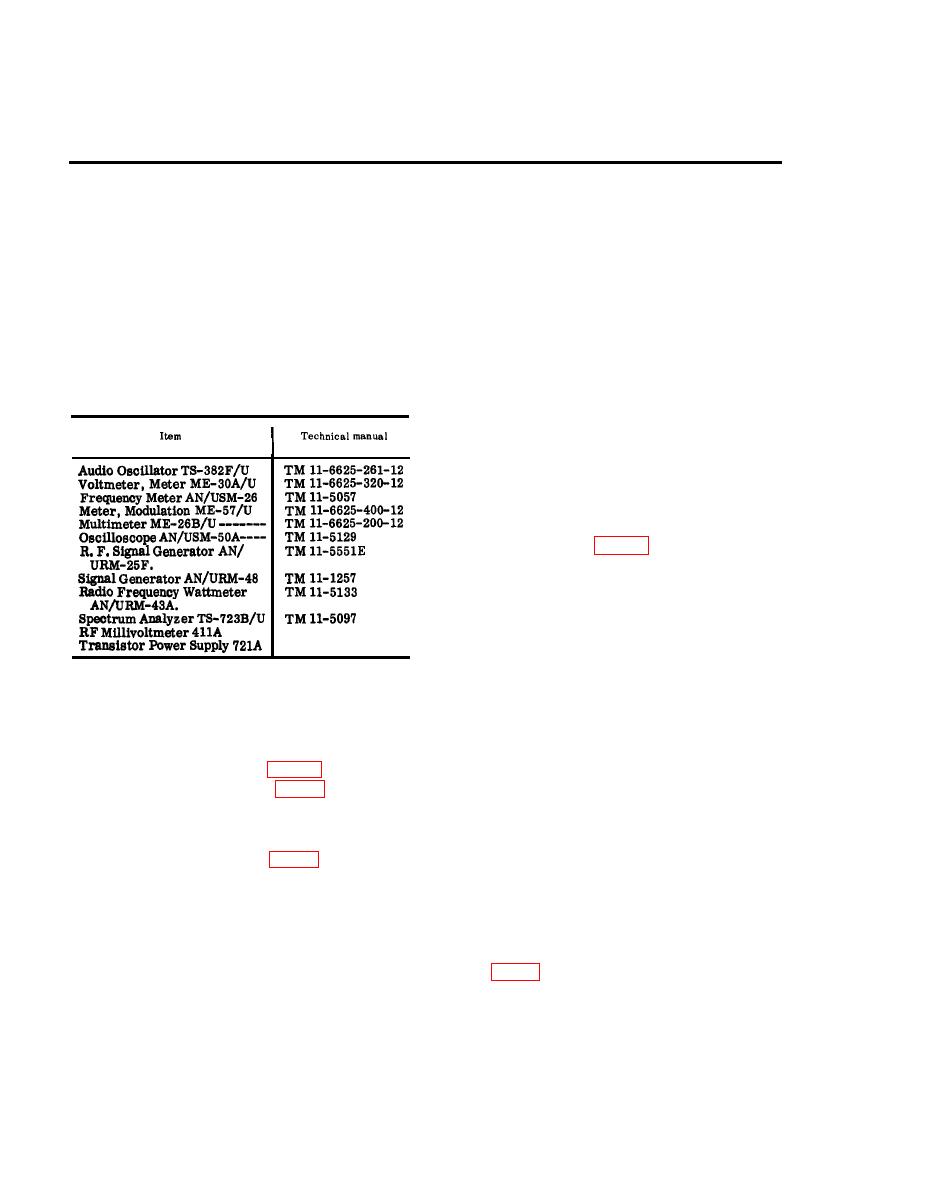
69. Test Equipment and Additional
specified is 29, 950 kc 5), set the fre-
Equipment Required
quency, by using the AN/USM-26, to the
a. Test Equipment.
exact number of significant figures desig-
nated.
known to be good) as a test set. When work-
ing on a module, remove the cover and
plug the module into the test set. When
alignment is required, replace those cov-
ers that have alignment holes. Use the
module extender (fig, 27) only when di-
rected.
(1). R e m o v e Battery Box CY-2562/
PRC-25 from the receiver-trans-
mitter case.
(2) Remove the receiver-transmitter
case from the receiver-transmit-
ter.
b. Additional Equipmen t Required.
(3) Connect the battery cable between
(1) Battery cable; a three-conductor
Battery, Dry BA-386/PRC-25 (that
cable of suitable length, with a bat-
is known to be good) and the battery
tery plug on one end, and a battery
plug on the receiver-transmitter.
receptacle on the other.
(4) Turn on the test equipment and al-
(2) Alignment cover (fig. 28).
low a 5-minute warmup period.
(3) ModuIe extender (fig. 27).
Caution: Do not place the re-
(4) Adapter UG-274B/U.
ceiver-transmitter in a transmit
(5) Resistor, 470-ohm, l-watt.
condition with a wattmeter con-
(6) Handset H-138/U.
nected or an antenna installed.
plate voltage is +150 volts dc. Take
70. GeneraI
all necessary precautions to pro-
tect personnel and test equipment.
Caution: Refer to the caution notice on
the inside front cover of this manual be-
fore connecting equipment or making tests.
a. The module assembly trouble isola-
tion procedures given in this chapter are
a. Preparation.
organized to localize and isolate trouble
(1) Prepare the following equipment:
in defective modules of the RT-505/PRC-
(a) Multimeter ME-26B/U.
25. A separate procedure is provided for
(b) Handset H-138/U.
|
|
Privacy Statement - Press Release - Copyright Information. - Contact Us |
