 |
|||
|
|
|||
|
Page Title:
Section IV. THIRD ECHELON ALIGNMENT |
|
||
| ||||||||||
|
|  Section IV. THIRD ECHELON ALIGNMENT
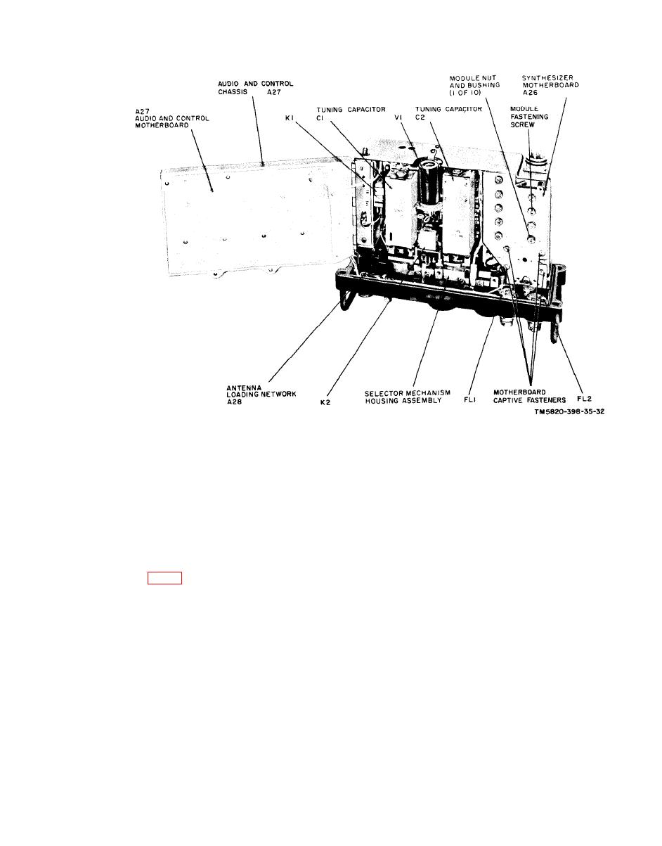
Note: Third echelon alignment consists of aligning transmitter power amplifierTank module A2, variable
frequency oscillator module A9, and sidestep oscillator module A20.
of one of the receiver-transmitter AUDIO
Tank Module A2
connectors.
e. Adjust A2T1 for a maximum indica-
tion on the ME-26B/U.
a. Set the rf output of the AN/URM-48
f. Set the rf output of the AN/URM-48
for 30.00 mc, modulated 10 kc by a 1,000 -
for 52.95 mc, modulated 10 kc by a 1,000-
cycle-per-second (cps) tone.
cps tone.
b. Connect the RF output lead of the AN/
g. Set the receiver-transmitter tuning
URM-48 to receiver-transmitter ANT jack
controls for 52.95 mc.
J2 .
h. Adjust A2C1 for a maximum indica-
c. Set the BAND switch of the receiver-
tion on the ME-26B/U.
transmitter at 30-52, and the tuning con-
i. Repeat c through h above until no
trols for 30.00 mc.
further increase in the ME-26B/U meter
d. Adjust the ME-26B/U to measure ac
indication can be obtained.
voltage and connect it across pins A and B
|
|
Privacy Statement - Press Release - Copyright Information. - Contact Us |
