 |
|||
|
|
|||
|
Page Title:
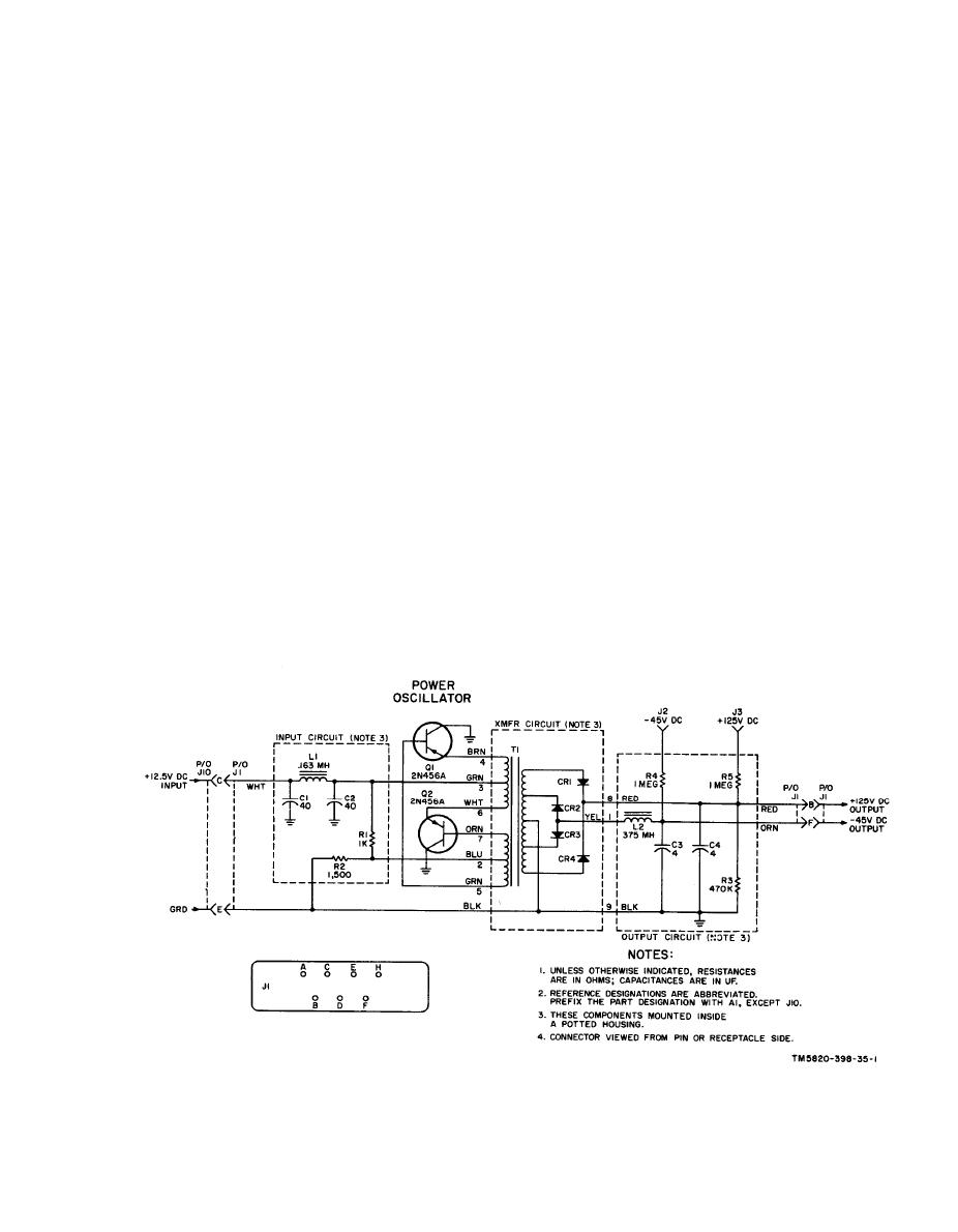
Figure 26. Dc-to-dc converter module A1, schematic diagram. |
|
||
| ||||||||||
|
|  used in conjunction with Test Set, Elec-
this test point, with no signal being re-
tronic Plug-in Circuit AN/GRM-55 to iso-
ceived, is 20 millivolts.
late a faulty module at the organizational
e. Module A6. Module A6 has one test
level. If usedproperly, however, the signal
point: J2. Test point J2 permits the rf
voltages at these test points will expedite
signal input to A6 (from A7) to be checked.
maintenance effort at higher echelons. A
A typical rf signal level at this test point,
listing of the modules which are equipped
with the RT-505/PRC-25 in transmit con-
with test points and a description of the
dition, is 3 volts.
signal to be expected at the test point are
f. Module A7. Module A7 has one test
given below.
point: J2. Test point J2 permits the rf sig-
a. Module A1. Module A1 has two test
nal input to A7 (from A8) to be checked. A
points: J2 and J3. Test point J2 permits
typical rf signal level at this test point,
the -45-volt output of the converter to be
with the RT-505/PRC-25 in transmit con-
checked. Test point J3 permits the +125-
dition, is 1.5 volts.
volt output of the converter to be checked.
g. Module A8. Module A8 has one test
b. Module A3. Module A3 has one test
point: J2. Test point J2 permits the rf in-
point: J2. Test point J2 permits the rf
put from the transmitter mixer (in A9) to
signal input to A3 (from A2) to be checked.
be checked. A typical rf signal level at this
A typical rf signal level at this test point,
test point, with the RT-505/PRC-25 in
with a 20-millivolt, 65-mc signal injected
transmit condition, is 0.5 volt.
h. Module A9. Module A9 has two test
at the ANT connector, is 25 millivolts.
points: J3 and J4. Test point J3 permits
c. Module A4. Module A4 has one test
point: J2. Test point J2 permits the rf
the input apc voltage (from A11) to be
signal input to A4 (from A3 to be checked).
checked. A typical apc voltage level, with
A typical rf signal level at this test point,
the vfo properly aligned, is +3.8 volts dc.
with a 20-millivolt, 65-mc signal injected
Test point J4 permits the output of vfo Q1
at the ANT connector, is 80 millivolts.
(in A9) to be checked. A typical rf signal
level of the vfo is 0.3 volt.
d. Module A5. Module A5 has one test
i. Module A10. Module A10 has two test
point: J2. Test point J2 permits sampling
the vfo input. A typical rf signal level at
points: J2 and J3. Test point J2 permits
39
|
|
Privacy Statement - Press Release - Copyright Information. - Contact Us |
