 |
|||
|
|
|||
|
Page Title:
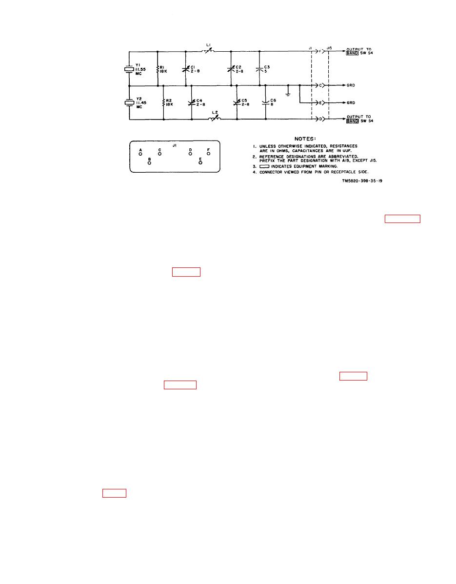
Transmitter First Rf Amplifier Module A8 |
|
||
| ||||||||||
|
|  A8 amplifies the rf input from variable
emitter. Inductor L3 and capacitor
frequency oscillator module A9 (para 15).
C13 form a filter network to pre-
a. The signal from A9 is coupled from
vent rf leakage into the power sup-
the top of the tapped secondary of T1
ply.
through coupling capacitor C2 to the emit-
c. Transmitter Mixer Q2.
ter of Q1 and from the bottom of the sec-
(1) The transmitter mixer functions
ondary of T1 through coupling capacitor
only during transmission. The sso
C3 to the base of Q1. The output at the
input from A20 (para 14) is applied
collector is coupled through BAND switch
through isolation resistors R8 and
SIB to either the low- or high-band tuned
R16 and coupling capacitor C3 to
output circuit.
the base of Q2. The vfo output is
b. Separate tuned output circuits are
applied through isolating resistors
used for the high and low bands. Switch S1
R10 and R16 and coupling capacitor
selects the circuit when the BAND switch
C3 to the base of Q2. Resistor R4
on the front panel is positioned.
is a dc return. The two signals are
(1) Low band. The low-band tuned out-
heterodyned in this stage; the out-
put circuit consists of inductor T2,
put from the collector is applied to
fixed capacitor C7, trimmer ca-
transmitter first rf amplifier mod-
pacitor C6, and ganged tuning ca-
ule A8. The collector returns to
pacitor C1C (fig. 88).
ground through the primary of T1
(2) High band. The high-band tuned
in module A8 (para 16).
output circuit consists of trans-
(2) Voltage divider resistors R5 and
former T3, fixed capacitor C10,
R6 develop the fixed bias for Q2.
trimmer capacitor C9, and ganged
Resistor R7 is the emitter swamp-
tuning capacitor C1C.
ing resistor. Capacitor C5 is an
c. Capacitors C4 and C5 and inductor
emitter rf bypass capacitor for the
L3 form a filter which prevents rf varia-
Q2. Inductor L1 and capacitor C6
tions from reaching the -45-volt dc supply.
form a filter network to prevent rf
The combination of resistors R2 and R3
leakage into the power supply.
provides fixed bias, and resistor R1 is the
emitter swamping resistor for Q1. Induc-
tors L1 and L2 are rf chokes. Capacitor
Module A8
C8 is inserted into the high-band output
tuned circuitry by S1C to shift the effective
Transmitter first rf amplifier module
range of ganged tuning capacitor C1C by
|
|
Privacy Statement - Press Release - Copyright Information. - Contact Us |
