 |
|||
|
|
|||
|
Page Title:
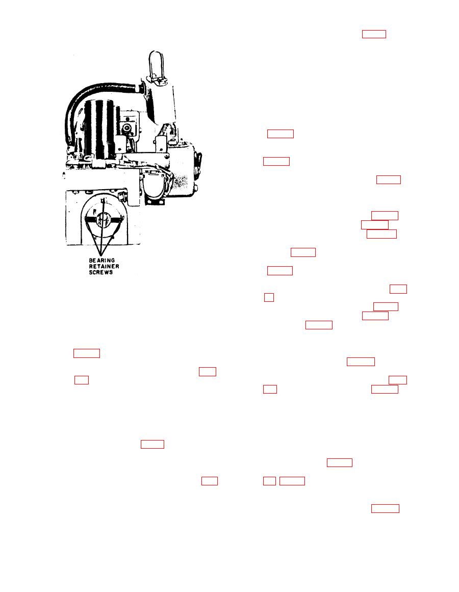
Figure 95. Rf and power amplifier subunit, front view |
|
||
| ||||||||||
|
|  d r i v e r rotor shaft (3, fig. 7 4 ) .
Tighten the setscrew.
(7) Center the capacitor rotors axially
on the rf tuning, the driver, and the
power amplifier rotor assemblies
so that the rotor plates are
centered between the stator plates.
(8) Rotate the rotors of the tuning ca-
pacitors to the right until the trail-
ing edges of the rotors of Z101,
Z103, Z105, Z106, Z107, and Z108
p l a t e s of each tuning capacitor.
(9) Tighten the setscrews (4 and 6,
fig. 70).
h. Replacement of Tube Chassis.
(1) Align points 2, 3, 4, and 5 (fig. 73)
a n d replace the four retaining
screws that fasten the tube chassis
to the power amplifier.
(2) Tighten the setscrew (5, fig. 70).
(3) Solder capacitor C145 (fig. 73) to
the plate clip of V105 (fig. 70).
(4) Solder coil L114 to the terminal
lug (1, fig. 73) .
(5) Replace the ground terminal to 2
(fig. 69).
(6) Solder the green, brown, orange,
TM5820-222-35-101
and red leads to the points 1 (fig.
72) .
(7) Solder the purple lead to 7 (fig. 70).
front view.
(8) Solder capacitor C106 (fig. 71) to
the Z101 (fig. 74) terminal.
power amplifier rotor shaft from
(9) Align relay K101 with the holes in
the rear of the chassis.
the relay mounting plate, insert the
Replace the bearing housing (2,
(2)
relay push rod, and replace the two
retaining screws (3, fig. 69).
the holes in the bearing retainer.
(10) Connect the wire and ribbon leads
Replace the three screws (1, fig.
(3)
of capacitors C105 and C110 (fig.
to the housing.
Align the screw holes in the tube
(4)
Caution: Do not place any strain
chassis with the standoffs on the
on the ribbon lead of the ceramic
power amplifier chassis, and re-
capacitor, or the capacitor will be
p l a c e the four retaining screws
damaged.
that fasten the two chassis together
(11) Repeat the operations outlined in
(2, 3, 4, and 5, fig. 73).
P u s h the driver rotor shaft up
( 1 0 ) above to solder capacitors
(5)
against the rf tuning rotor shaft.
C114 and C117 (fig. 71) to the Z103
Align the flats of both shafts and
terminal through the space marked
tighten the setscrew (5 and 6, fig.
70) that engages each shaft.
(12) Repeat the operations outlined in
Align the flat of the power amplifier
(10) and (11) above to s older ca-
(6)
rotor shaft with the setscrew on the
pacitors C121 and C123 (fig. 71)
142
|
|
Privacy Statement - Press Release - Copyright Information. - Contact Us |
