 |
|||
|
|
|||
|
Page Title:
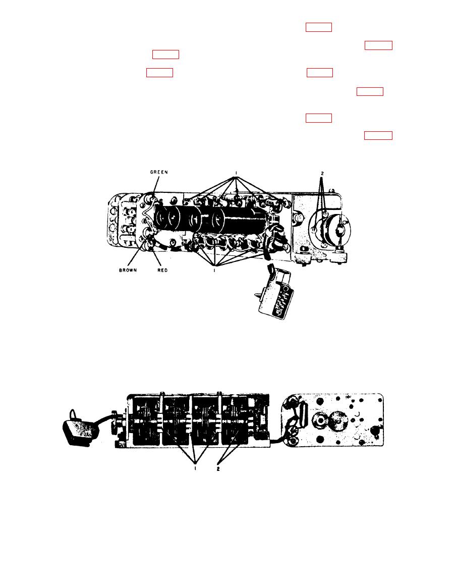
Figure 94. Uhf injection subunit, bottom view, cover plate removed, first oscillator folded out. |
|
||
| ||||||||||
|
|  and C117 (fig. 71) from the Z103
leads of the fixed capacitors from
terminal. Insert the soldering iron
the junctions. Separate the ribbon
tip through the space 10 (fig. 70).
lead of the ceramic capacitor from
(5) Repeat the operation outlined in (3)
the Z101 terminal (fig. 74). Insert
above to separate capacitors C121
the soldering iron tip through the
and C123 (fig. 71) from the Z105
space marked 11 (fig. 70).
terminal. Insert the soldering iron
Caution: Do not place any strain
tip through the space 9 (fig. 70).
on the ribbon lead of the ceramic
(6) Repeat the operation outlined in (3)
capacitor, or the capacitor will be-
above to separate capacitors C 126
come damaged. Avoid overheating
and C139 (fig. 71) from the Z106
the junction.
terminal. Insert the soldering iron
tip through the space 8 (fig. 70).
(4) Repeat the operation outlined in (3)
(7) Remove the two retaining screws
above to separate capacitors C114
TM5820-222-35-90
first oscillator cover plate removed.
TM5820-222-35-93
140
|
|
Privacy Statement - Press Release - Copyright Information. - Contact Us |
