 |
|||
|
|
|||
|
Page Title:
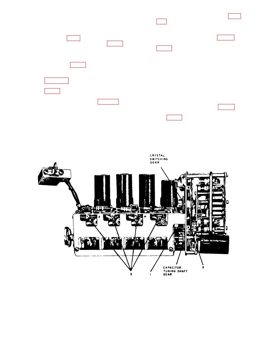
Removal and Replacement of Frequency Multiplier-Amplifier Assembly |
|
||
| ||||||||||
|
|  from the rt unit main frame (para
tuning shaft and crystal switching
gears are mechanically synchron-
(2) Remove the cover plate by loosen-
ized.
ing the two screws (2) and remov-
Replace the retaining screw
(2)
ing the two screws (3, fig. 92).
marked 3 (fig. 90) and the two re-
(3) Carefully heat the four junctions (2,
taining screws marked 1 (fig. 91).
fig. 90); withdraw the wire lead of
Refit the cover plate over the first
(3)
the fixed capacitor and the ribbon
oscillator assembly and replace
lead of the ceramic capacitor from
t h e six Phillips-head screws
each joint.
marked 1 (fig. 92).
Resolder the red, brown, and green
(4)
Caution: Do not place any strain
leads to the junctions as shown in
on the ribbon lead of the ceramic
capacitor, or the capacitor will be
Resolder the lead to the junction (1,
(5)
damaged. Avoid overheating the
junctions.
Replace the uhf injection subunit in
(6)
(4) Unsolder and disconnect the lead
the rt unit mainframe (para 108 b ).
from the junction (1) (fig. 90).
(5) Remove the 12 retaining screws
(1, fig. 93) and pull the frequency
Multiplier-Amplifier Assembly
multiplier-amplifier assembly off
the main casting of the uhf injection
a. Removal.
(1) Remove the uhf injection subunit
subunit.
TM5820-222-35-89
|
|
Privacy Statement - Press Release - Copyright Information. - Contact Us |
