 |
|||
|
|
|||
|
Page Title:
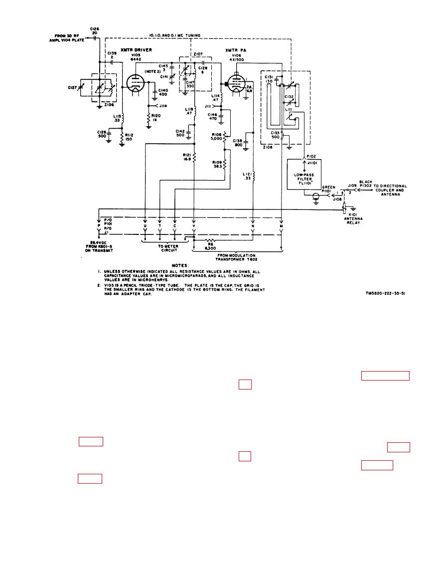
Modulator Driver V804 and Transmitter Modulator V804 through V808 |
|
||
| ||||||||||
|
|  modulator driver. Tubes V805, V806,
the screen grid. Plate voltage is supplied
V807, and V808 perform a dual purpose as
to V803 through plate load resistor R824.
the receiver output amplifier and the
Note. In some rt units, L803 has been substituted
transmitter modulator. On transmit, each
for R850.
stage functions as described in paragraphs
b. The audio output signals developed
across load resistor R824 are coupled
plied to the stages is approximately 300
through C813, potentiometer R843, con-
volts dc on transmit and the drive level is
tacts 1 and 20 of tr relay K802 (energized
increased. Thus, the output power of these
on transmit), contacts 9 and 14 of squelch
stages is higher on transmit than on
relay K801 (deenergized on transmit) to the
receive.
control grid of modulation driver stage
b. The modulated B+ supplied to the
V804 (fig. 14).
plates of transmitter driver V105 (para
mitter power amplifier V106 (para 56) is
Modulator V804 through V808
tapped off the primary winding (terminal
2) of output transformer T802. Jack J803
is a test point for measuring the modulated
a. Tube V804 performs a dual purpose as
B+. The metering circuit connected across
the second receiver audio amplifier and the
37
|
|
Privacy Statement - Press Release - Copyright Information. - Contact Us |
