 |
|||
|
|
|||
|
Page Title:
Section III. HIGH-LEVEL RF AND MODULATOR STAGES |
|
||
| ||||||||||
|
|  (3) Contacts 3-5 open and prevent any
signal from being fed from the plate
erate the following circuits:
of V104 to first if. amplifier V301.
(1) Contacts 1-2 close grounding the rf
c. The output of V104 is coupled through
avc line.
C126 and Z106 to V105 (para 55).
(2) Contacts 6-7 open. This action pre-
vents the 200-370-mc uhf signal
from being applied to the cathode of
Scheme
V104. On transmit, only the rf sig-
nal from second rf amplifier V103
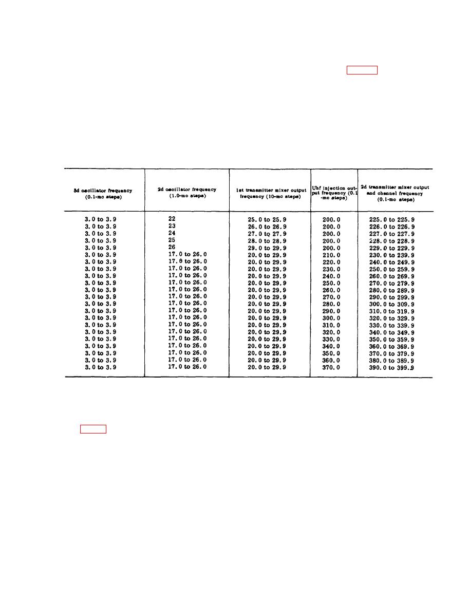
The following chart correlates the dial
is applied to the cathode of V104.
settings with the oscillator and mixer cir-
Tube V104 functions as an rf am-
c u i t frequencies used in the low-level
plifier when the rt unit is used for
stages of the rt unit. This chart applies
transmission.
only to the transmit function.
Section Ill. HIGH-LEVEL RF AND MODULATOR STAGES
grounded grid amplifier. Coil L115 pro-
vides the cathode impedance for the input
signal and resistor R112 provides cathode
a. The amplified rf output of V104 is cou-
bias for V105. Capacitor C129 is a cathode
pled to parallel-tuned circuit Z106 by ca-
bypass capacitor. Capacitor C140 provides
pacitor C126. The tuned circuit provides a
rf ground for the grid of V105 and resistor
high-impedance to the 225.0- to 399.9-mc
R120 is the grid-return circuit to ground.
frequencies. Capacitor C127 is a trimmer
Jack J114 is a test point for measuring
for Z106. The signal voltage developed
grid bias on V105 developed by the rf sig-
across the tuned circuit is coupled through
n a l . Transmitter driver V105 receives
capacitor C139 to the cathode of transmit-
modulated plate voltage from the +300-volt
t e r driver V105, which functions as a
|
|
Privacy Statement - Press Release - Copyright Information. - Contact Us |
